
Connector for flexible substrate

a flexible substrate and connector technology, applied in the direction of coupling contact members, coupling device connections, coupling/disassembly parts, etc., can solve the problems of high cost, hinder the downsizing of the whole connector, and contact easily lose resilience, etc., to achieve high dustproof effect and high performance

Inactive Publication Date: 2007-09-20
HOSIDEN CORP
View PDF7 Cites 5 Cited by
  • Summary
  • Abstract
  • Description
  • Claims
  • Application Information

AI Technical Summary

Benefits of technology

[0007]However, in the above-described conventional example, when the contacts are made shorter in length, they tend to fail to provide a predetermined contact pressure and contacts easily lose resilience, which would hinder the downsizing of the whole connector. However, if a highly elastic material is used for the contacts, this poses another problem of high cost.
[0008]The present invention is devised under the above-described background, and an object of the present invention is to provide a connector for a flexible substrate in which a desired contact pressure is obtained without causing increases in size and cost.
[0010]In a connector for a flexible substrate in accordance with an aspect of the present invention, when the end portion is inserted into the board insertion port of the housing, it is received by the arm portions of the contacts, and when the actuator is rotated to thereby press the cam portions against the arm portions of the contacts, the contact point portions of the contacts are brought into pressure contact with the electrodes on the surface of the flexible substrate. At this time, because the entire arm portions are elastically deformed to support the end portion of the flexible substrate, a large contact pressure can be obtained. Consequently, a predetermined contact pressure can be maintained without employing long contacts or highly elastic, and the invention brings about a significant advantage in the downsizing and cost reduction of the whole connector.
[0011]In a connector for a flexible substrate in accordance with an aspect of the present invention, since cam portions of first type of the actuator may contact with the upper sides of tip portions of upper linear portions of the arm portions of the contacts, and the contact points of the contacts are arranged in positions on the board-insertion-direction side as compared with the cam portions of the first type, the entire arm portions of the contacts significantly contract in accordance with the rotation of the actuator, and a large force acts on the contact point portions of the contacts, resulting in larger contact pressure.
[0013]In a connector for a flexible substrate in accordance with an aspect of the present invention, since contacts have rotary shaft holding portions for holding rotary shafts of the actuator, the invention may totally or partly dispense with parts for preventing the pull-out of the actuator and for pivotally supporting the same, which simplifies the construction of the connector resulting in reduced cost.
[0015]In a connector for a flexible substrate in accordance with an aspect of the present invention, even when end portions of the contacts on the board-insertion-direction side are exposed from a side of the housing opposite to the board insertion port, the side of the housing is covered with a dustproof cover portion when the actuator is in a closed state. Therefore, the invention brings about a high dustproof effect and high performance.

Problems solved by technology

However, in the above-described conventional example, when the contacts are made shorter in length, they tend to fail to provide a predetermined contact pressure and contacts easily lose resilience, which would hinder the downsizing of the whole connector.
However, if a highly elastic material is used for the contacts, this poses another problem of high cost.

Method used


Image

  • Connector for flexible substrate
  • Connector for flexible substrate
  • Connector for flexible substrate

Examples


Embodiment Construction

[0021]Hereinafter, an embodiment of a connector for a flexible substrate according to the present invention is described with reference to the drawings.

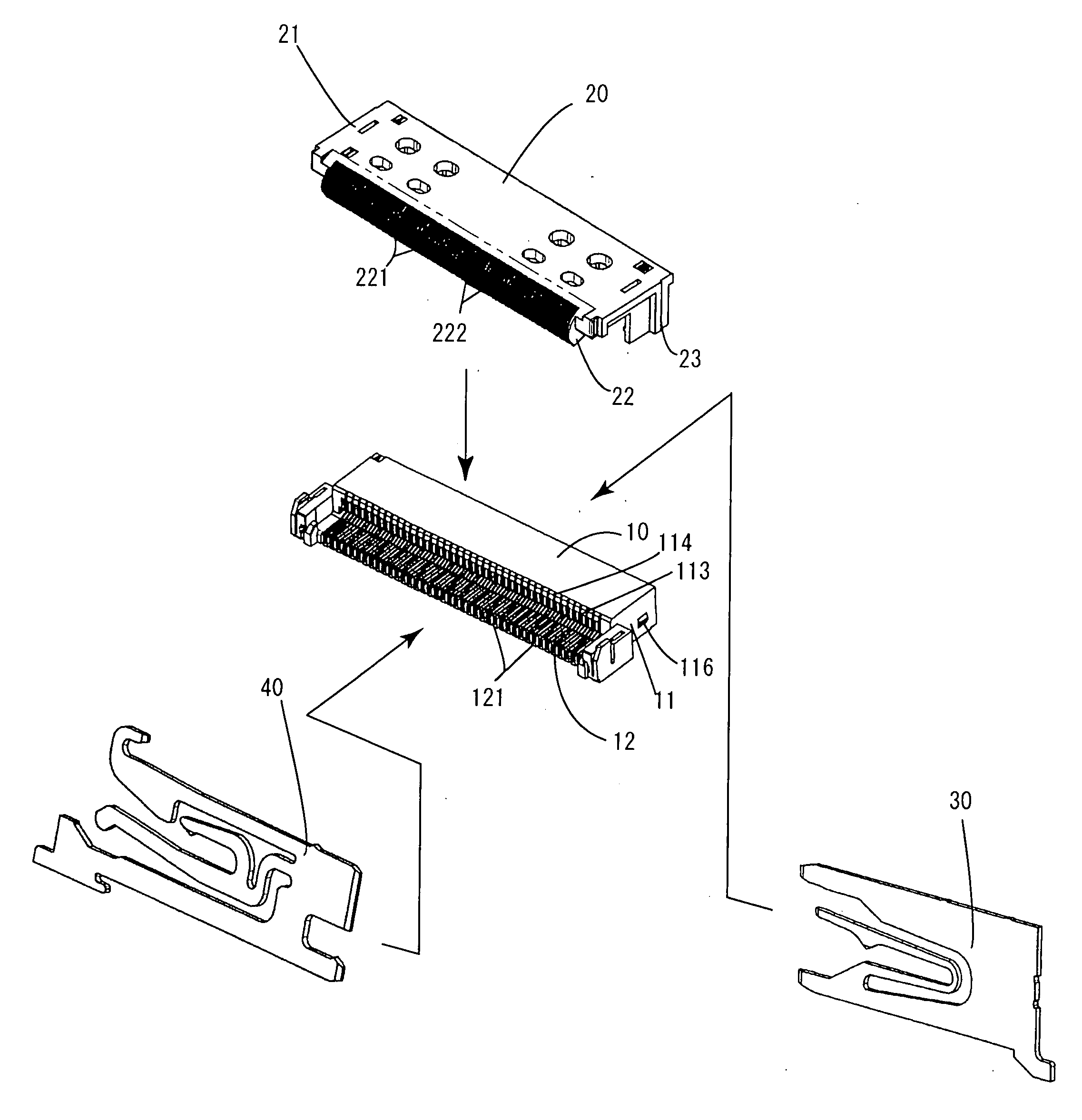
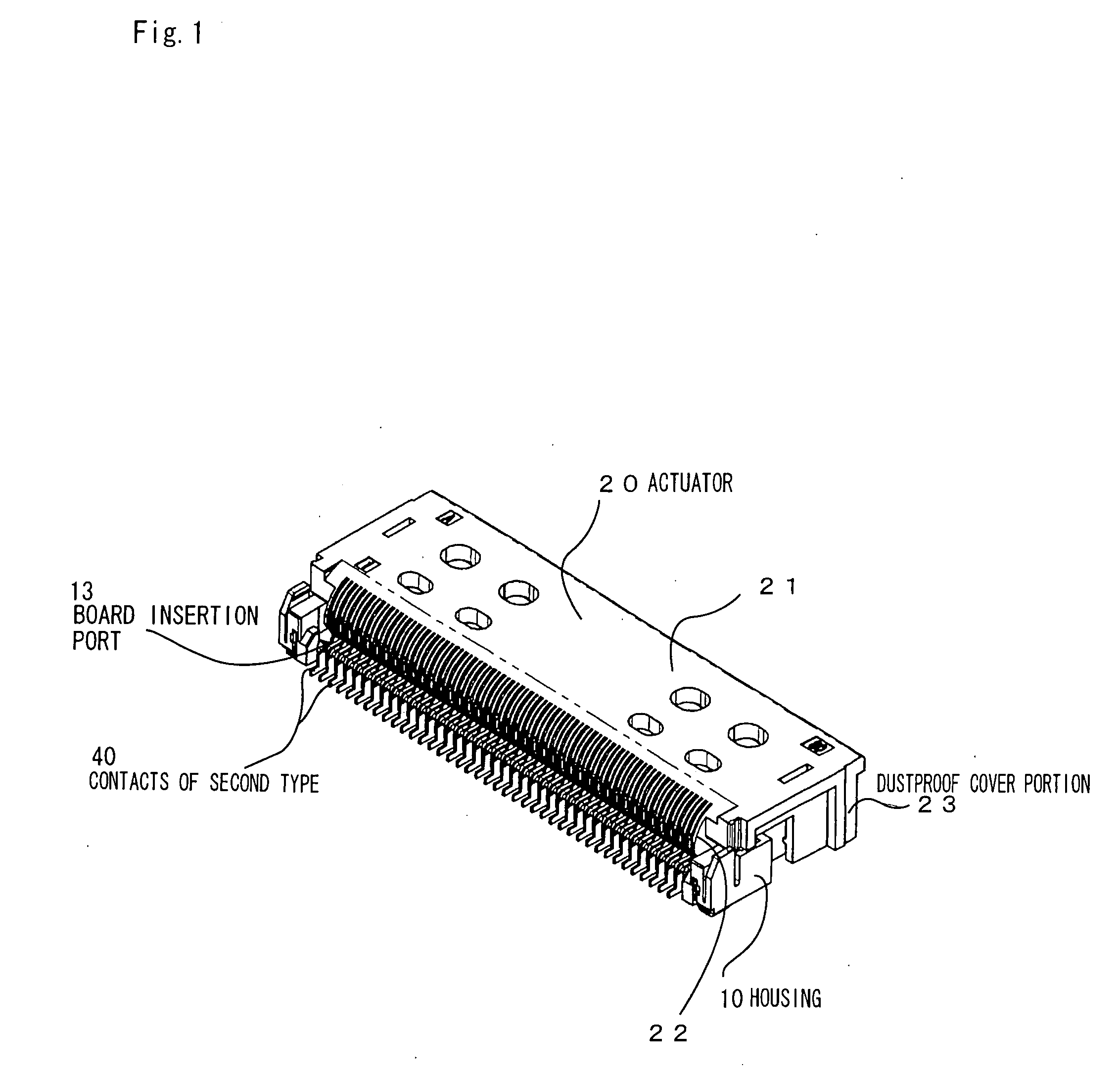
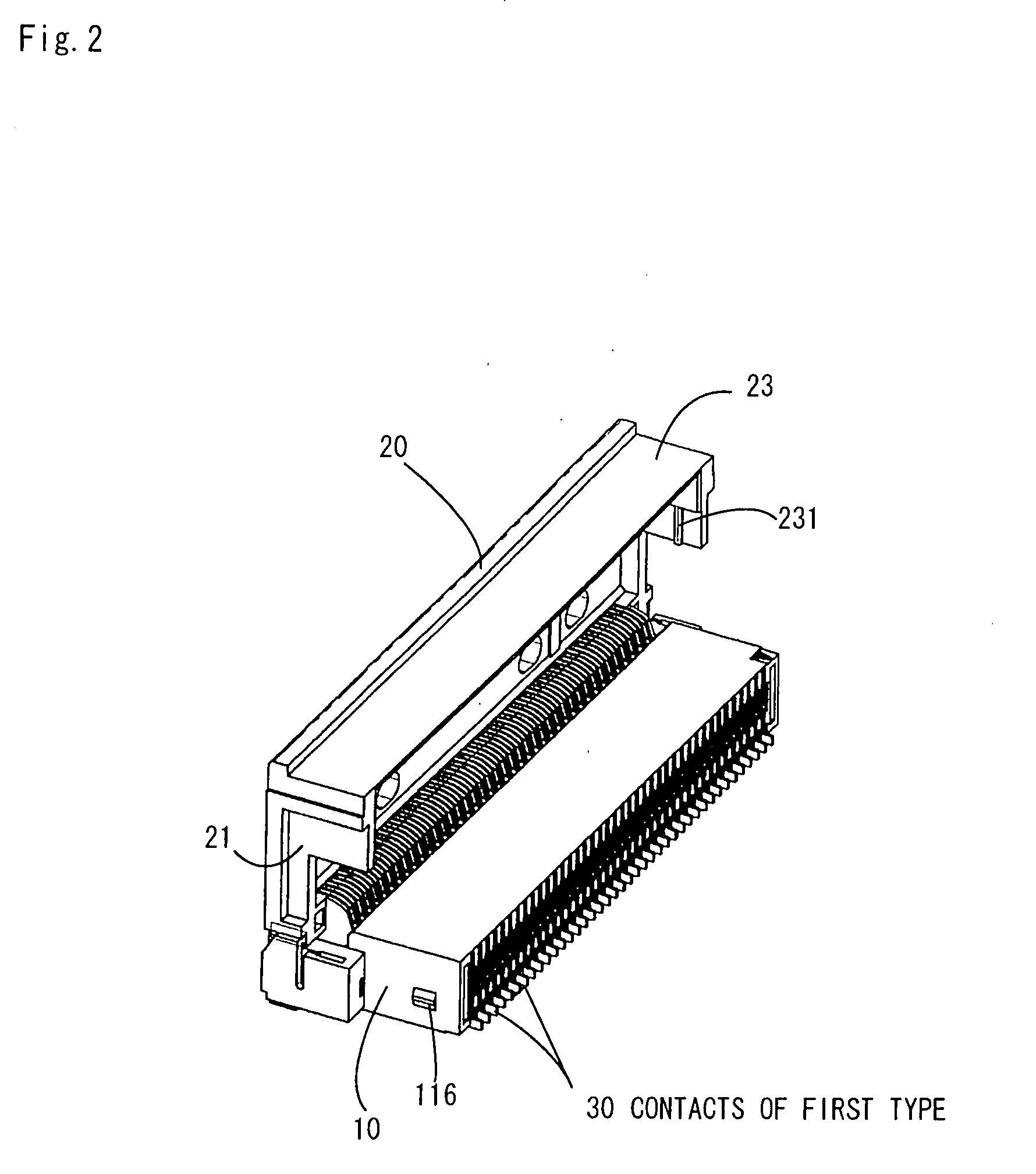
[0022]FIG. 1 is a perspective view showing a closed state of a connector for a flexible substrate, FIG. 2 is a perspective view showing an opened state of the same connector, FIG. 3 is an exploded perspective view of the connector, FIG. 4 is cross-sectional views of the connector showing a shape of a contact of the first type thereof, and FIG. 5 is cross-sectional views of the connector showing a contact of the second type thereof connector.

[0023]The connector for a flexible substrate cited here is a board mounting type connector that electrically connects a flexible substrate α (refer to FIGS. 4 and 5). At the end of the upper surface of this flexible substrate α, there are arranged in a width direction with electrodes not shown, which match the internal core wires in number and form two rows in a length direction of the board.

[0024...


PUM


Abstract

A connector for a flexible substrate of the present invention includes a housing having a board insertion port for receiving a flexible substrate, contacts of first and second types provided in parallel with each other inside the housing and supported pivotally and rotatably on an upper side of the housing and provided with cam portions, the cam portions being adapted to directly or indirectly press the contacts for bringing the contacts into pressure contact with the electrodes of the flexible substrate when the actuator is rotated to be put into a closed state. The contacts of the first and second types each has a base portion attachable to a back portion of the board insertion port of the housing, and an arm portion having a substantially U-shaped side view, being supported in midair by the base portion and being adapted to support an end portion of the flexible substrate.

Description

[0001]The present application claims priority under 35 U.S.C. §119 of Japanese Patent Application No. 2006-073719 filed on Mar. 17, 2006, the disclosure of which is expressly incorporated by reference herein in its entity.BACKGROUND OF THE INVENTION[0002]1. Field of the Invention[0003]The present invention relates to a connector for a flexible substrate that is connected to an end portion of a flexible substrate.[0004]2. Description of the Related Art[0005]As this type of connector for a flexible substrate, there is exemplified a connector including a housing formed with a board insertion port for receiving a flexible substrate, contacts provided in parallel with each other so as to be contactable with electrodes of the flexible substrate inside the housing, and an actuator supported pivotally and rotatably on the upper side of the housing.[0006]The contacts in this case are elastic plate-like pieces having E-shaped side views, the lower slit of which is adapted to receive an end po...

Claims


Application Information

Patent Timeline
IPC IPC(8): H01R12/00H01R12/79
CPCH01R12/79H01R12/88H01R23/661H01R13/5213H01R13/193H01R12/77
Inventor KATO, RYUHEI
Owner HOSIDEN CORP
Learn More