Connector having a pivoting member with enhanced dust proofing

a technology of pivoting member and dust-proofing, which is applied in the direction of coupling contact member, coupling device connection, coupling/disconnecting part engagement/disengagement, etc., can solve the problems of failure or defective electrical connection, use of connectors, etc., and achieve the effect of improving the dust-proof property

Inactive Publication Date: 2007-08-21
DDK LTD
View PDF9 Cites 16 Cited by
  • Summary
  • Abstract
  • Description
  • Claims
  • Application Information

AI Technical Summary

Benefits of technology

[0019]It is an object of the invention to provide a connector which can fully comply with the requirements particularly recently imposed on connectors and overcome the drawbacks of the prior art and which requires zero insertion force for a connecting object such as a flexible printed circuit board and achieves improved dust-proof property.
[0026](3) According to the invention, the pivoting member 18 has a substantially U-shaped cross-section, and a gap between the tip of the upper wall 52 and the actuating portion 56 is 0.5 to 0.7 mm and a gap between the upper wall 52 and the tip of the pivoting member 18 on the opposite side from the actuating portion 56 is 0.3 to 0.5 mm, thereby avoiding the pivoting member 18 from touching the upper wall 52 of the housing 12 upon pivotal movement of the pivoting member 18 and improving the dust-proof property of the connector. Accordingly, as there is little or no gap between the pivoting member and the housing, it is possible to improve the dust-proof property to the extent more than two to three times that of the Patent Literature 6.
[0027](4) At least one of the first and second pieces 22, 24 of each of the contacts 14, and the contacts 14, 16 of the one and the other kinds is provided with an inclined portion 28 tilted downwardly seen from the fitting opening 20. Therefore, it achieves a reduced overall height of the connector of 2.5 mm or less.

Problems solved by technology

Depending upon uses or applications of the connectors, however, there is no need for miniaturization (reduced overall height), and therefore, the dust-proofing of the connector would be degraded by the exposed contacts, which may cause defective or failed electrical connection as the case may be.
Furthermore, sometimes connectors are used under bad circumstances such as dusty environment.

Method used


Image

  • Connector having a pivoting member with enhanced dust proofing
  • Connector having a pivoting member with enhanced dust proofing
  • Connector having a pivoting member with enhanced dust proofing

Examples


Embodiment Construction

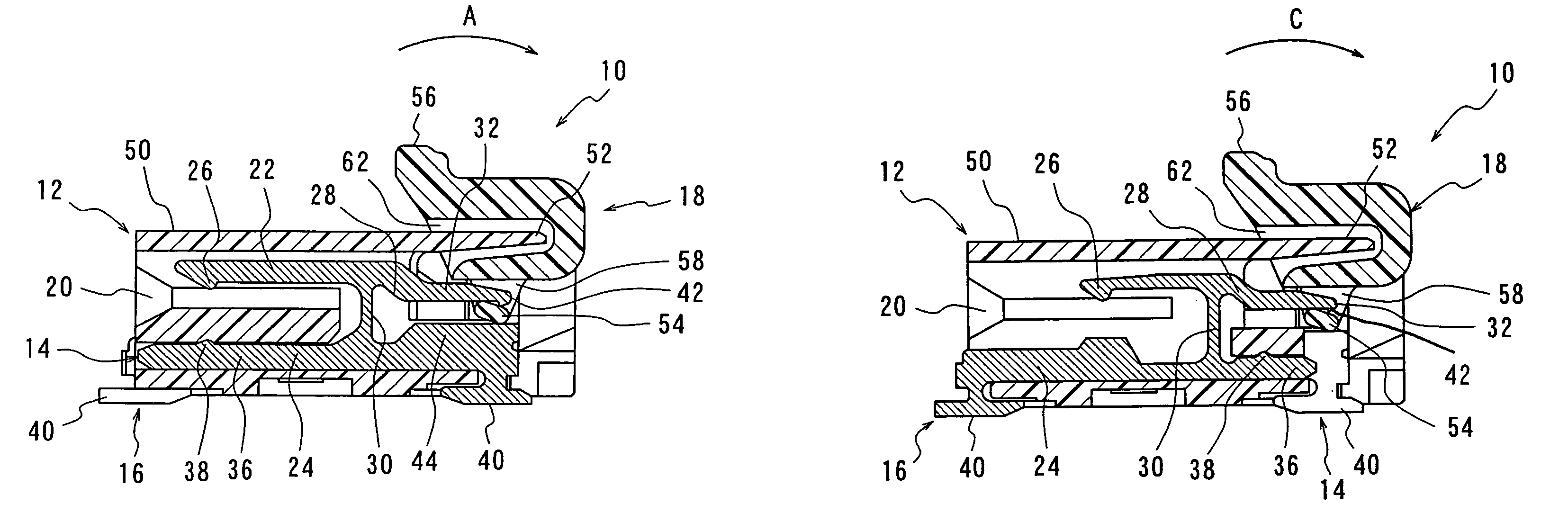
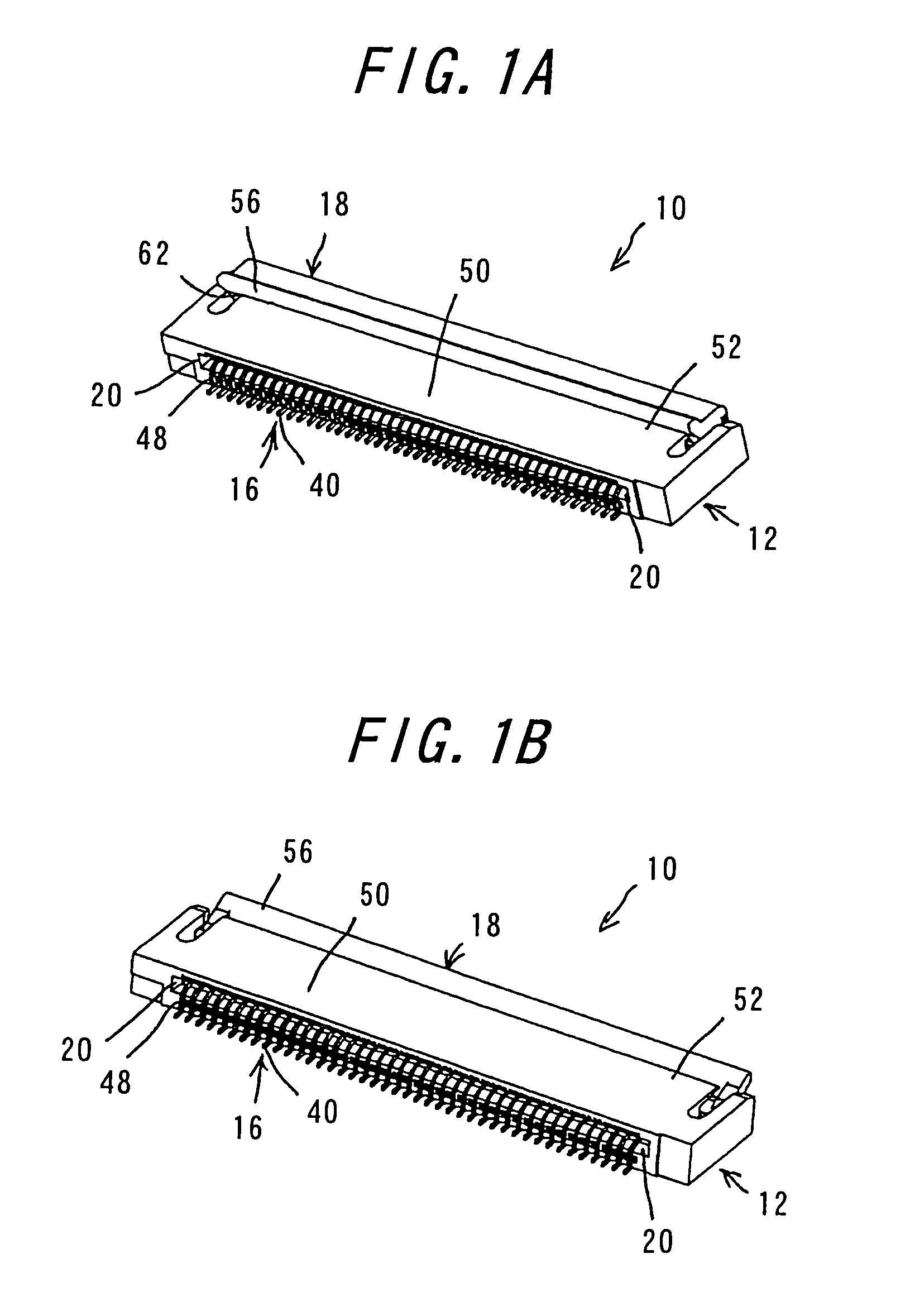
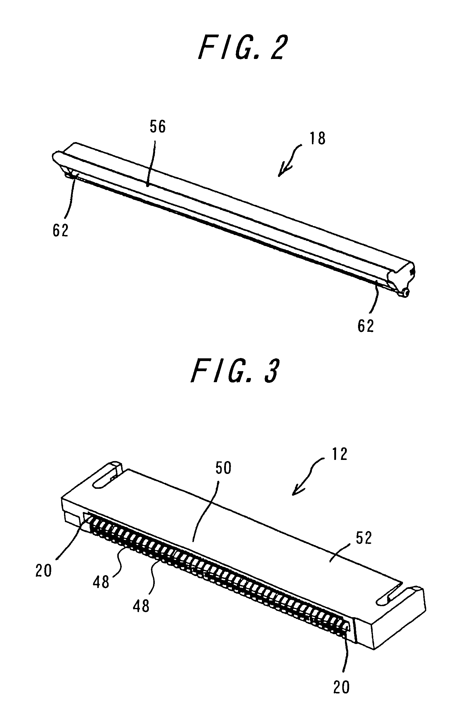
[0042]One embodiment of the invention will be explained with reference to FIGS. 1A to 8E. FIG. 1A is a perspective view of a connector according to the invention with a pivoting member opened, viewed from the side of the fitting opening for a flexible printed circuit board. FIG. 1B is a perspective view of the connector with the pivoting member closed. FIG. 2 is a perspective view of the pivoting member and FIG. 3 is a perspective view of a housing. FIG. 4A is a perspective view of a contact of one kind and FIG. 4B is a perspective view of a contact of the other kind. FIG. 5A is a sectional view of the connector with the pivoting member opened, taken along the contact of the one kind. FIG. 5B is a sectional view of the connector with the pivoting member closed, taken along the contact of the one kind. FIG. 6A is a sectional view of the connector with the pivoting member opened, taken along the contact of the other kind. FIG. 6B is a sectional view of the connector with the pivoting ...


PUM


Abstract

A connector includes contacts having a contact portion, a connection portion, a fulcrum portion, a jointing portion and a pressure receiving portion; a housing having a ceiling portion covering the contact portions of the contacts and an upper wall covering the pressure receiving portions; and a pivoting member having an actuating portion, urging portions, anchoring holes and a cover portion. Pivotal movement of the urging portions between the connection portions and the pressure receiving portions brings the contact portions into contact with a connecting object. Gaps between the tip of the upper wall and the actuating portion and between the upper wall and the tip of the lower part of the pivoting member are made narrow so that the pivotally moving pivoting member does not touch the upper wall of the housing, thereby enhancing dust-proofing and achieving no insertion force for flexible printed circuit board.

Description

BACKGROUND OF THE INVENTION[0001]The present invention relates to a connector using a flexible printed circuit board for use in electric and electronic appliances such as flat-screen or thin-shaped plasma televisions, notebook personal computers and the like, and more particularly to a connector superior in dust-proofing.[0002]Connectors used in mobile phones, charge coupled device (CCD) cameras and the like generally include conductors arranged in narrow pitches and are very thin (a so-called lighter, more compact). A connector of one type mainly comprises a housing and contacts, and a flexible printed circuit board is inserted into the housing to force the circuit board into contact with the contacts (a so-called non-zero-insertion force type). A connector of another type mainly comprises a housing, contacts, and a slider, and a flexible printed circuit board is embraced between the housing and a slider (a so-called zero-insertion-force type). Various methods can be considered for...

Claims


Application Information

Patent Timeline
Patent Type & Authority Patents(United States)
IPC IPC(8): H01R13/15H01R13/62
CPCH01R12/88
Inventor FUKAZAWA, TAKEKI
Owner DDK LTD
Why Eureka
Try Eureka