
Variable geometry flexible support systems and methods for use thereof

a flexible support system and variable geometry technology, applied in the direction of gymnastic exercise, frictional force resistor, sport apparatus, etc., can solve the problems of fixed stride length not ideally simulating all weight bearing exercise activities, the elliptic path is typically restricted by the crank, and the elliptic path is too short for tall users,

Active Publication Date: 2007-09-20
RODGERS JR ROBERT E
View PDF49 Cites 49 Cited by
  • Summary
  • Abstract
  • Description
  • Claims
  • Application Information

AI Technical Summary

Benefits of technology

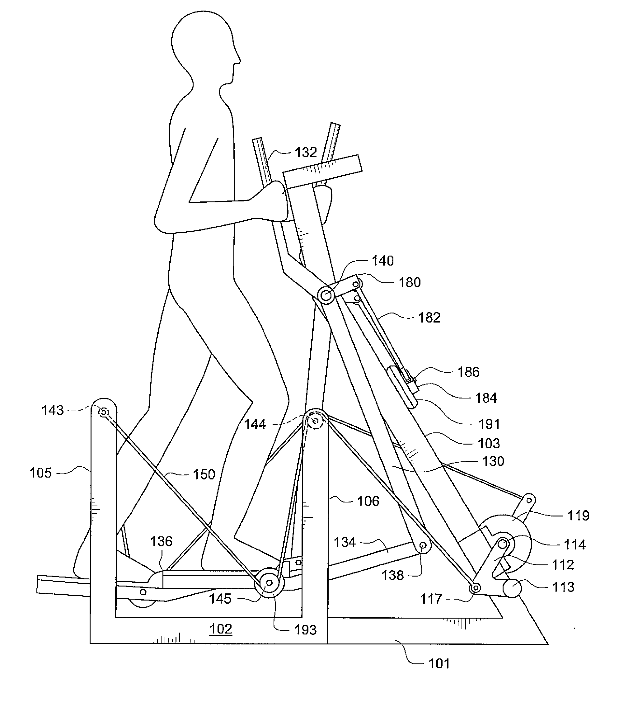
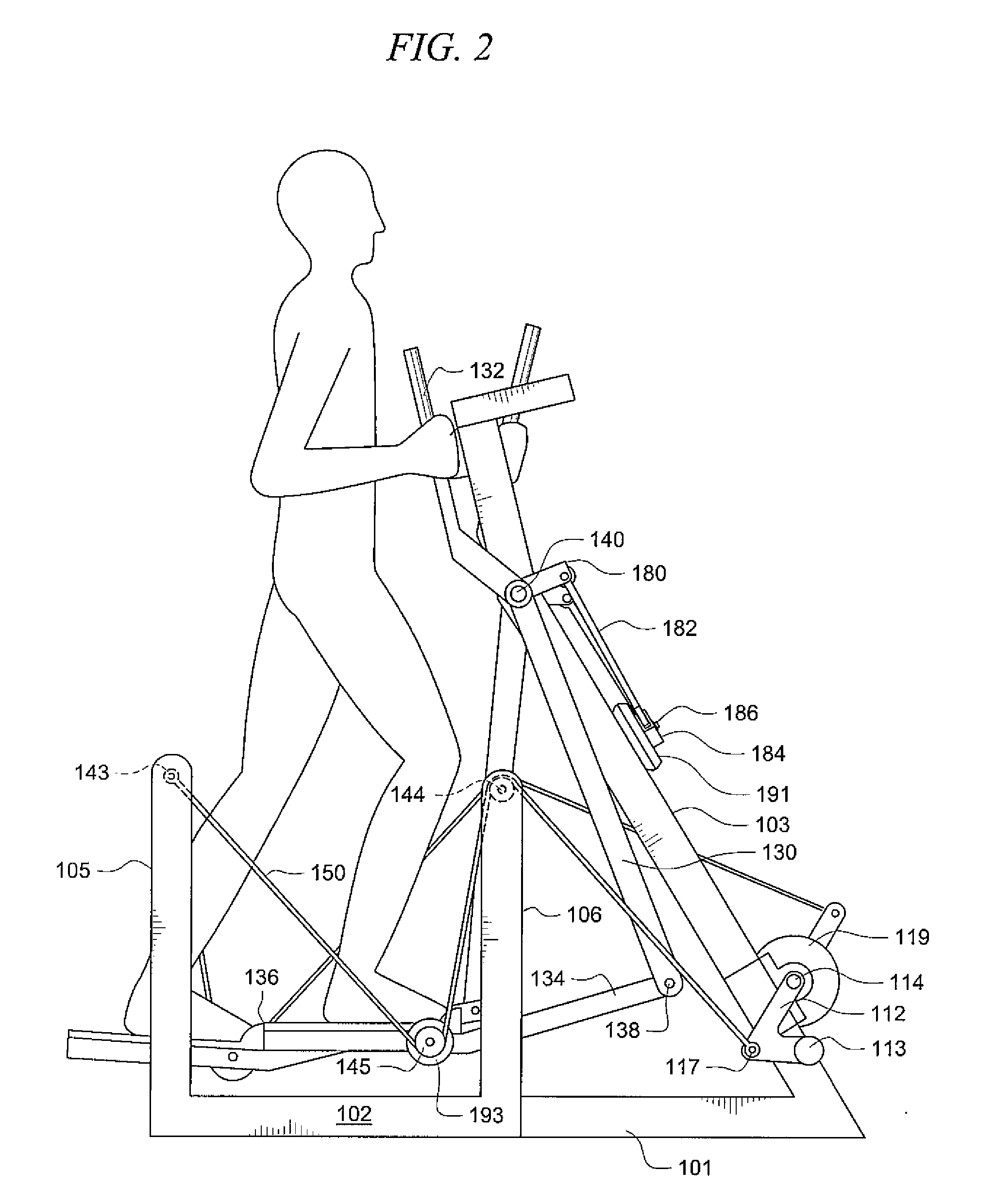
[0008] An exercise device according to the present invention may be used by applying force to the right and left foot support members, thereby changing the geometric relationship between the foot support members and other portions of the device. The changed geometry causes the flexible element to rotate at least a portion of the crank system. In some embodiments, striding motion applied to the foot support members causes the foot support members to trace substantially closed paths.

Problems solved by technology

However, rigid coupling to a crank typically constrains the elliptic path to a fixed length.
Therefore, the elliptic path may be too long for shorter users, or too short for tall users.
Further, a running stride is typically longer than a walking stride, so a fixed stride length does not ideally simulate all weight bearing exercise activities.
Therefore, typical elliptic machines cannot optimally accommodate all users.
Such a motion does not accurately simulate walking, striding, or jogging, where the user's feet typically lift and lower.
Such a motion does not accurately simulate a wide range of real world climbing activities such climbing stairs or climbing sloped terrain.
These devices, however, may be complex and have high manufacturing costs.

Method used


Image

  • Variable geometry flexible support systems and methods for use thereof
  • Variable geometry flexible support systems and methods for use thereof
  • Variable geometry flexible support systems and methods for use thereof

Examples


Embodiment Construction

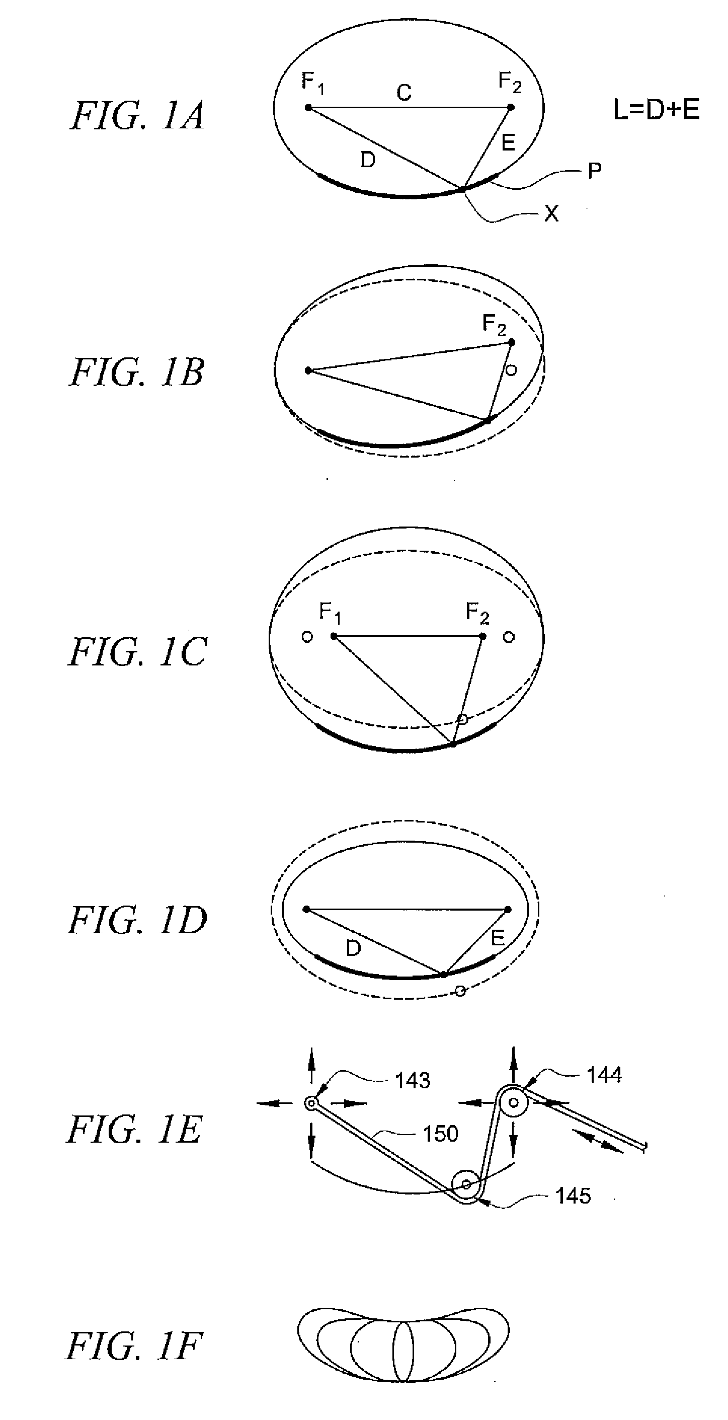
[0026] In the following detailed description, reference is made to the accompanying drawings, in which are shown by way of illustration specific embodiments of the present invention. It should be understood that the detailed description and specific examples are intended for purposes of illustration only and are not intended to limit the scope of the invention. Numerous changes, substitutions, and modifications may be made without departing from the scope of the present invention.

[0027]FIG. 1A shows an example of a geometric system that generates a path P of point X in space. Two focal points are defined as F1 and F2. Line segment C connects F1 to F2, line segment D connects F1 to X, and line segment E connects F2 to X. The lengths of line segments D and E sum to distance L. Path P is the locus of points where the distance L remains constant as X traverses through space. Path P according to the above constraints is a perfect mathematical ellipse.

[0028]FIG. 1B shows an example of a...


PUM


Abstract

An exercise apparatus comprises: a frame having a base portion and having first and second right support elements and first and second left support elements; a crank system comprising first and second crank coupling locations, the crank system being supported by the frame; a right foot support member; a left foot support member; a right guide element coupled to the right foot support member and; a left guide element coupled to the left foot support member; a first flexible support system comprising a first flexible element, the first flexible element coupled to the first and second right support elements and the right guide element and coupled to the first crank coupling location; and a second flexible support system comprising a second flexible element, the second flexible element coupled to the first and second left support elements and the left guide element and coupled to the second crank coupling location, wherein alternating motion of the right and left foot support members causes the first and second crank coupling locations to rotate.

Description

CROSS-REFERENCE TO RELATED APPLICATIONS [0001] This application claims priority to U.S. Provisional Patent Applications Ser No. 60 / 780,599 filed on Mar. 9, 2006 entitled “BELT AND CRANK EXERCISE DEVICE” and Ser. No. 60 / 881,205 filed on Jan. 19, 2007, entitled “LINKAGE AND BRAKE SYSTEMS”, the disclosures of which are hereby incorporated by reference.TECHNICAL FIELD [0002] The present description relates generally to an exercise device and, more particularly, it relates to an exercise device with a variable geometry flexible support system. BACKGROUND OF THE INVENTION [0003] It can be appreciated that exercise devices have been in use for years and include devices that simulate walking or jogging such as cross country ski machines, elliptic motion machines, and pendulum motion machines. Also included are exercise devices that simulate climbing such as reciprocal stair climbers. [0004] Elliptic motion exercise machines provide inertia that assists in direction change of the pedals, whi...

Claims


Application Information

Patent Timeline
IPC IPC(8): A63B22/04
CPCA63B21/0051A63B21/008A63B21/012A63B21/151A63B2022/067A63B22/001A63B22/0015A63B22/0664A63B2022/0017A63B21/225A63B22/0017
Inventor RODGERS, JR., ROBERT E.
Owner RODGERS JR ROBERT E
Learn More