Tether apparatus

a technology of tethering device and tethering rod, which is applied in the direction of press-button fasteners, traveling carriers, travelling objects, etc., can solve the problems of difficult to secure a fastening device to the sheet material, restricting the movement of a sheet material in relation to an object, and being susceptible to displacemen

Inactive Publication Date: 2007-09-27
BRINSON JOHN K
View PDF15 Cites 25 Cited by
  • Summary
  • Abstract
  • Description
  • Claims
  • Application Information

AI Technical Summary

Benefits of technology

[0027]The present invention is defined by the appended claims with specific embodiments being shown in the attached drawings. For the purpose of summarizing the invention, the invention relates to an improved apparatus for coupling a sheet material to an object. The apparatus comprises a clip having a first jaw member and a second jaw member for grasping the sheet material. A strap extends between a first end and a second end. The first

Problems solved by technology

Since sheet material is often light and has a large surface area, the sheet material may be susceptible to displacement by an airstream and/or by a moving body that makes contact with the sheet material.
Restricting movement of a sheet material in relation to an object may prove to be problematic.
First, the sheet material may be relatively thin and flexible

Method used


Image

  • Tether apparatus
  • Tether apparatus
  • Tether apparatus

Examples


Embodiment Construction

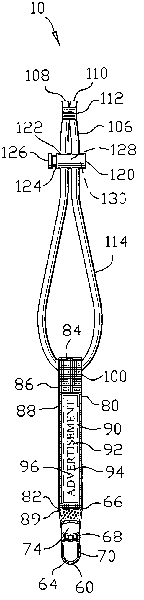
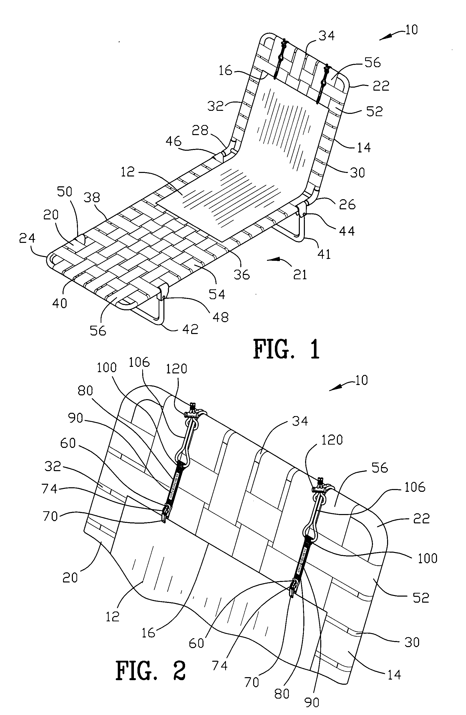
[0057]FIGS. 1 and 2 are isometric views of a tether apparatus 10 for coupling a sheet material 12 to an object 14. The object as shown in FIGS. 1-2 and 7-12 is a chair 20 that rests upon a floor 21. The chair 20 has a back 22 and a seat 24. The back 22 and seat 24 may either be rigidly jointed by welding, gluing, bolting or other similar fasteners or pivotably jointed by a first and second hinge 26 and 28. The back 22 may include a first back frame member 30, a second back frame member 32 and a back joining frame member 34. The seat 24 may include a first seat frame member 36, a second seat frame member 38 and a seat joining frame member 40. The seat 24 may be supported by a first leg 41 and a second leg 42. The first leg 41 may either be rigidly jointed by welding, gluing, bolting or other similar fasteners or pivotably jointed by a third and fourth hinge 44 and 46. The second leg 42 may either be rigidly jointed by welding, gluing, bolting or other similar fasteners or pivotably j...


PUM


Abstract

A tether apparatus is disclosed for coupling a sheet material to an object. The tether comprises a clip having a first jaw member and a second jaw member for grasping the sheet material. A strap extends between a first end and a second end. The first end of the strap is secured to the clip. The second end of the strap defines a closed loop. A continuous cord extends through the closed loop of the strap for encircling the object and enabling the clip to be inserted within the continuous cord for securing the continuous cord to the object. A keeper slidably engages the continuous cord for adjusting the length of the continuous cord by the position of the keeper on the continuous cord.

Description

BACKGROUND OF THE INVENTION[0001]1. Field of the Invention[0002]This invention relates to tethers and more particularly to an improved apparatus for coupling a sheet material to an object.[0003]2. Background of the Invention[0004]Sheet material has been utilized to provide many wide range of uses including but not limited to a cover to shield an object, a liquid absorbent layer, or clothing. In many instances restricting the movement of a sheet material in relation to an object is beneficial or even essential. Since sheet material is often light and has a large surface area, the sheet material may be susceptible to displacement by an airstream and / or by a moving body that makes contact with the sheet material.[0005]Restricting movement of a sheet material in relation to an object may prove to be problematic. First, the sheet material may be relatively thin and flexible proving it difficult to secure a fastening device to the sheet material. Second, the fastening device must be secur...

Claims


Application Information

Patent Timeline
IPC IPC(8): A44B21/00A44B99/00
CPCA41F19/00A45F5/00Y10T24/31A45F2005/006A45F5/02
Inventor BRINSON, JOHN K.
Owner BRINSON JOHN K
Why Eureka
Try Eureka