Fire Suppression System

a fire suppression system and sprinkler technology, applied in fire rescue, medical science, dental surgery, etc., can solve the problems of unfinished residential basements, thermoplastic sprinkler piping near the initial fire location, and the possibility of structural failure of fire suppression systems, so as to achieve more cost-effective effects

Inactive Publication Date: 2007-09-27
LUBRIZOL ADVANCED MATERIALS INC
View PDF14 Cites 127 Cited by
  • Summary
  • Abstract
  • Description
  • Claims
  • Application Information

AI Technical Summary

Benefits of technology

This patent discusses new sprinkler systems that work better in small fires and allows for the use of thermoplastic pipes like CPVC. These systems can even be installed in unfinished basements where there's no ceiling yet. Overall, these systems make sure that people are safe by effectively suppressing fire outbreaks.

Problems solved by technology

The technical problem addressed in this patent relates to designing effective fire suppression measures utilizing sprinkler systems which require meeting specific safety standards for their placement and operation.

Method used


Image

  • Fire Suppression System
  • Fire Suppression System
  • Fire Suppression System

Examples


Embodiment Construction

[0023]The foregoing summary, as well as the following detailed description of exemplary embodiments, will be better understood when read in conjunction with the appended drawings. For the purpose of illustrating the exemplary embodiments, there is shown in the drawings certain exemplary systems. It should be understood, however, that these embodiments are merely exemplary and that the present invention is not limited to the systems, arrangements and instrumentalities shown or described herein.

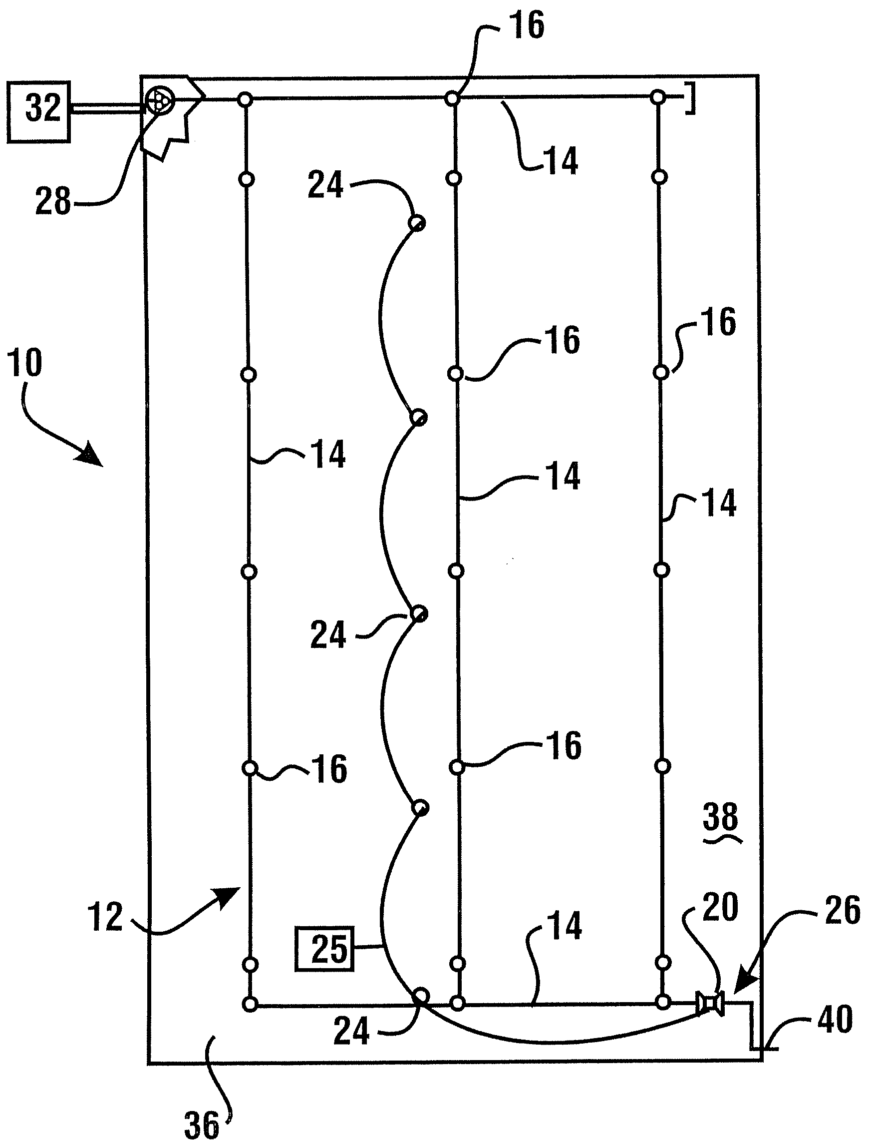
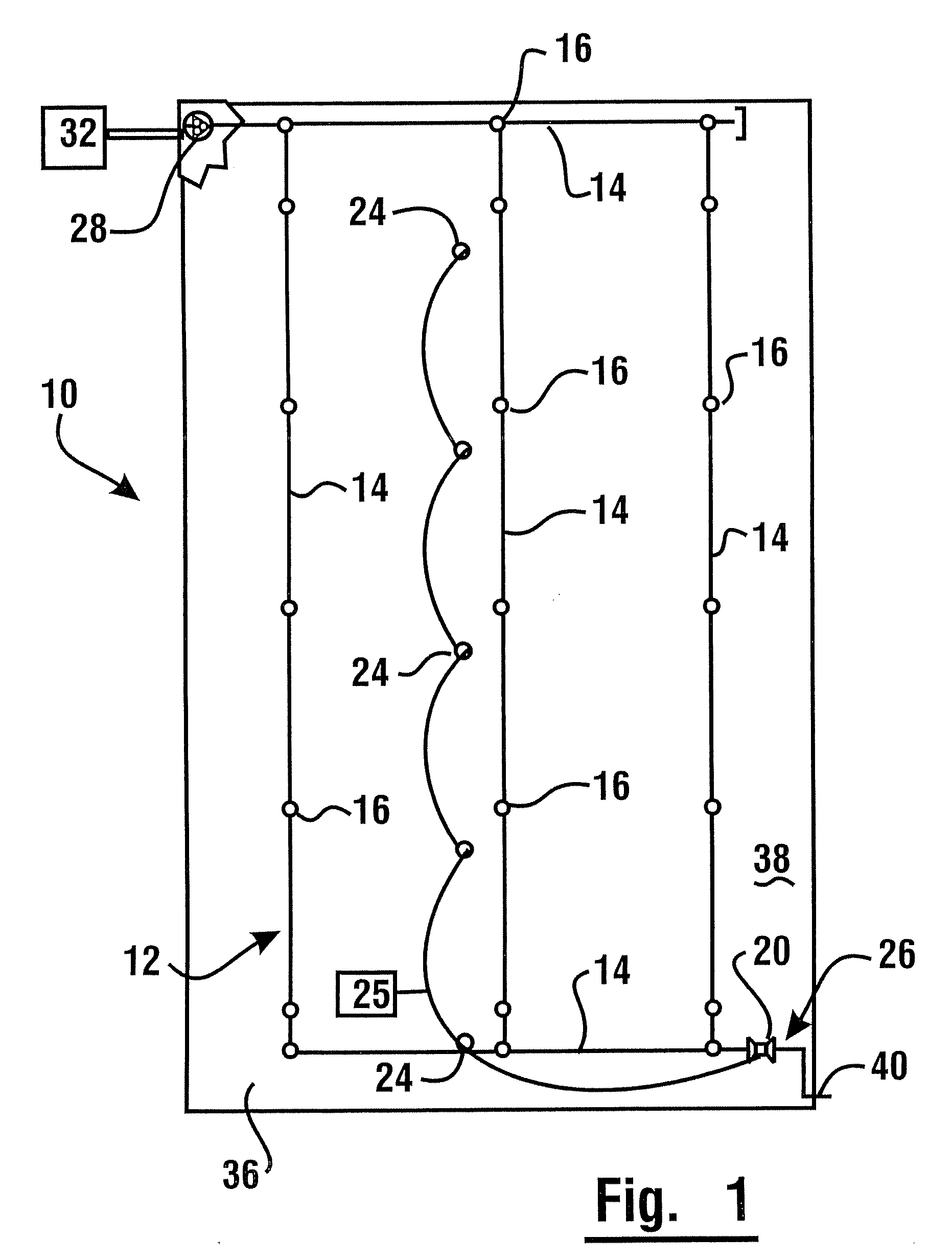
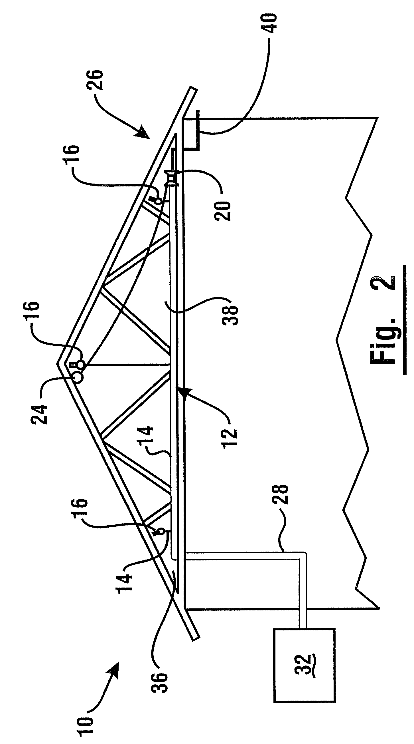
[0024]With respect to the Figures, in an exemplary embodiment, a fire suppression system 10 includes a sprinkler line 12 comprising a network of fluid conduits 14 which are formed of a thermoplastic material. In the exemplary embodiment, the fluid conduits are comprised of chlorinated polyvinyl chloride (CPVC). The fluid conduits (which are alternatively referred to herein as pipes) 14 are in flow communication with a plurality of fire sprinklers 16. The exemplary type of CPVC resin of which th...


PUM


Abstract

A sprinkler system comprises a network of CPVC conduits and a plurality of sprinklers. The system includes an electrically activated solenoid control valve to allow fluid to flow in the pipe network. One or more fire detectors operate independently of the condition of the sprinklers. Upon detection of an incipient fire situation, a fire detector sends an electrical signal to cause activation of the control valve. Upon activation of the control valve, fire suppression fluid is caused to flow through the conduits before the incipient fire situation matures into a sprinkler-triggering event. The cooling effect of fluid flowing through the conduit enables the conduit to resist structural failure prior to sprinkler deployment. The control valve may be disposed at a remote location in the sprinkler line and be operable as part of an inspector's test connection.

Description


Claims


Application Information

Patent Timeline
Owner LUBRIZOL ADVANCED MATERIALS INC
Why Eureka
Try Eureka