Method for covering an elongate object and device for covering said elongate object

a technology of elongate objects and devices, applied in the direction of electrically conductive connections, pipe elements, conductors, etc., can solve the problems of increasing complexity, accelerating cable ageing, and negatively affecting the mechanical properties of the connection of elongate elements

Active Publication Date: 2010-06-01
PRYSMIAN CAVI E SISTEMI ENERGIA
View PDF24 Cites 26 Cited by
  • Summary
  • Abstract
  • Description
  • Claims
  • Application Information

AI Technical Summary

Benefits of technology

[0038]The Applicant has perceived the need of providing a method for covering an elongate object which can be simply carried out by the technical personnel, even when operating in narrow areas such as in trenches (or manholes) dug in the soil, and which can ensure a satisfactory result in terms of providing an outer protective covering element in the splicing zone between two elongate elements.
[0039]Furthermore, the Applicant has perceived the need of providing a covering assembly which is easy to be manufactured and installed, and which also presents very limited dimensions, principally in the axial direction, so that the parking area—which is required during installation—can be advantageously reduced and the operations of the technical personnel inside of the trench can be advantageously improved.
[0040]Moreover, in the case a joint between to electric cables has to be performed, the Applicant has perceived the need of providing a covering assembly whose size and constructive features allow the technical personnel to easily operate on the metallic screens of the two cables to restore the electrical continuity thereof.
[0041]The Applicant has found that a covering assembly having small length and ease of installation can be obtained by providing the splicing zone of two elongate elements with a covering element which comprises—at each axial end thereof—at least two folded portions which are coaxially arranged and radially superimposed, said folded portions being supported in a pre-stretched condition on two different supporting elements during installation.
[0052]The Applicant has observed that the covering method of the present invention is particularly advantageous, for example with respect to the method disclosed in document EP-966,780, also for the reason that the presence of two folded portions at each axial end of the covering element allows to sensibly reduce the parking area of the covering assembly.

Problems solved by technology

In fact, since a joint is arranged and made operative in trenches dug in the ground, during installation the technical personnel has to operate in areas of very narrow dimensions and often in the presence of dust, moisture and / or debris accumulated along the edges thereof.
This aspect is particularly disadvantageous since the radially external surface of the outer elastic tubular portion of the covering element in the pre-stretched condition, i.e. when the covering element is parked on an elongate element end, comes into contact with dust, moisture and / or debris present in the trench, said impurities being thus transferred and trapped inside of the covering element when the latter is collapsed onto the elongate element during installation.
Said possible impurities contaminate the covering element and negatively affect the mechanical properties of the elongate elements connection.
In particular, the presence of said impurities decreases the sealing property of the covering element and some water can penetrate into the cable which possibly causes corrosion as well as problems of accelerated ageing of the cable with deterioration of the electric features thereof.
The Applicant has observed that this aspect contributes to increase the complexity of said method since during installation, which is manually carried out by technical personnel operating in the narrow areas mentioned above, the personnel has to remove the support—e.g. by pulling with one hand on the helically wound strip which forms the support—and to push the covering device with the other hand, preferably simultaneously.
As a consequence, the installation of such a covering device is complex and difficult to be performed.
Furthermore, the technical solutions described in document EP-966,780, in particular the covering device of FIG. 8 in which two different supports are provided so that an outer tubular portion of the folded elastic element is folded back over an inner tubular portion of the elastic element to form a circumferential fold, are difficult to be industrially obtained.
This operation is particularly difficult since the formation of the folded back portion is carried out at the maximum radial expansion thereof, with relatively high elastic forces to be overcome.

Method used


Image

  • Method for covering an elongate object and device for covering said elongate object
  • Method for covering an elongate object and device for covering said elongate object
  • Method for covering an elongate object and device for covering said elongate object

Examples


example 1

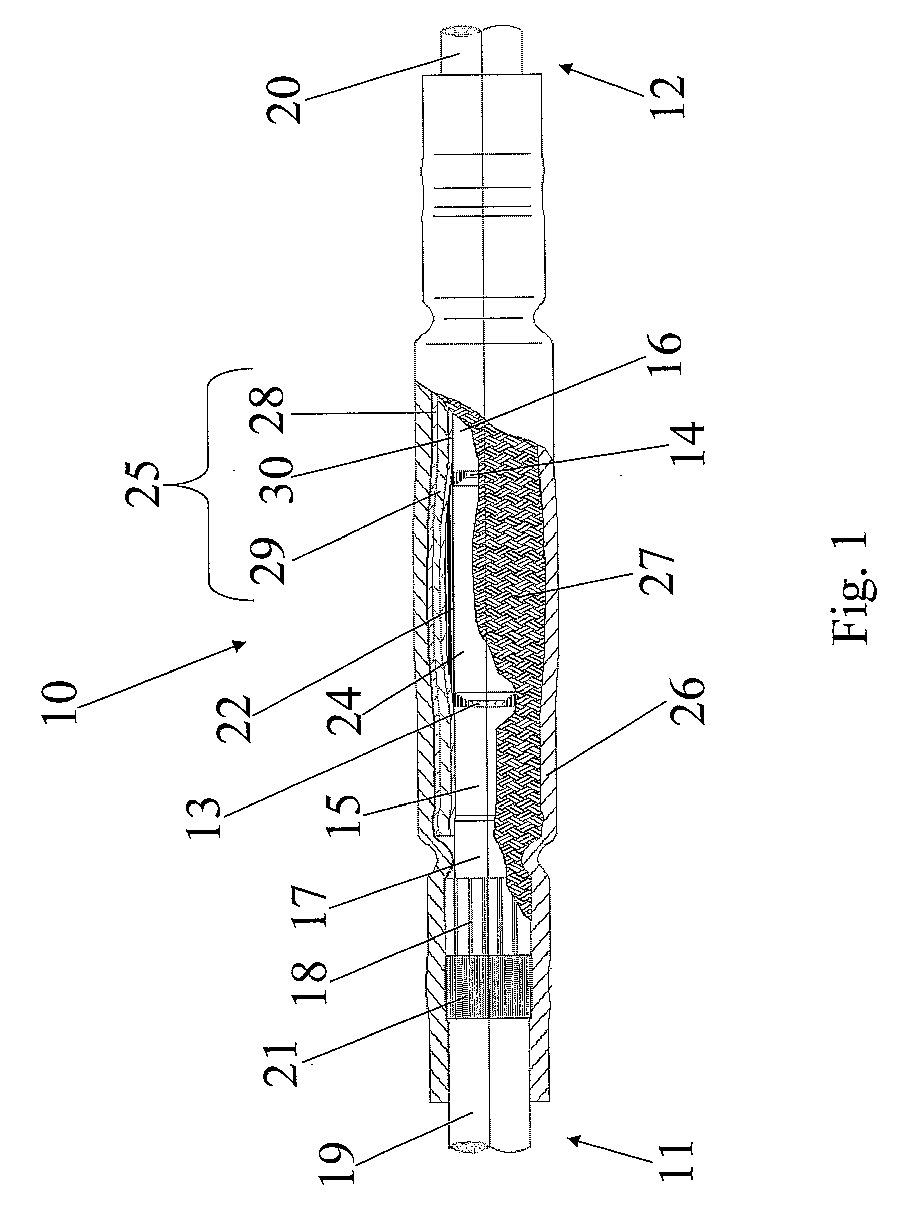
[0173]Two medium voltage electric cables were spliced by using the method of the present invention.

[0174]The cable features are reported in Table 1.

[0175]

TABLE 1Cable constitutive elementsCable featuresConductorcross-sectional area = 95 mm2Insulating Layerexternal diameter = 25.90 mmOuter semiconductive Layerexternal diameter = 27.90 mmMetallic screenexternal diameter = 31.00 mmExternal polymeric sheathexternal diameter = 37.00 mm

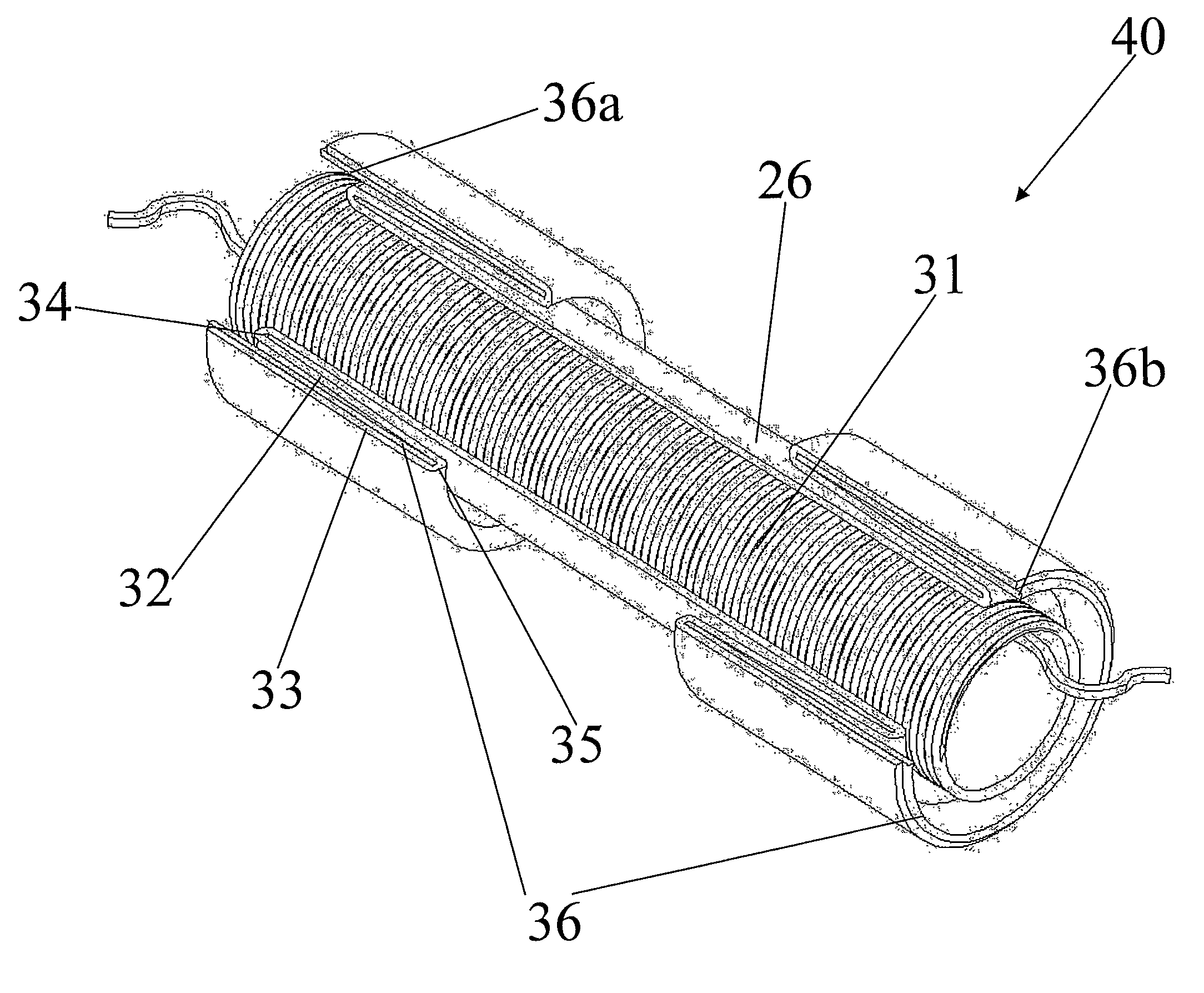
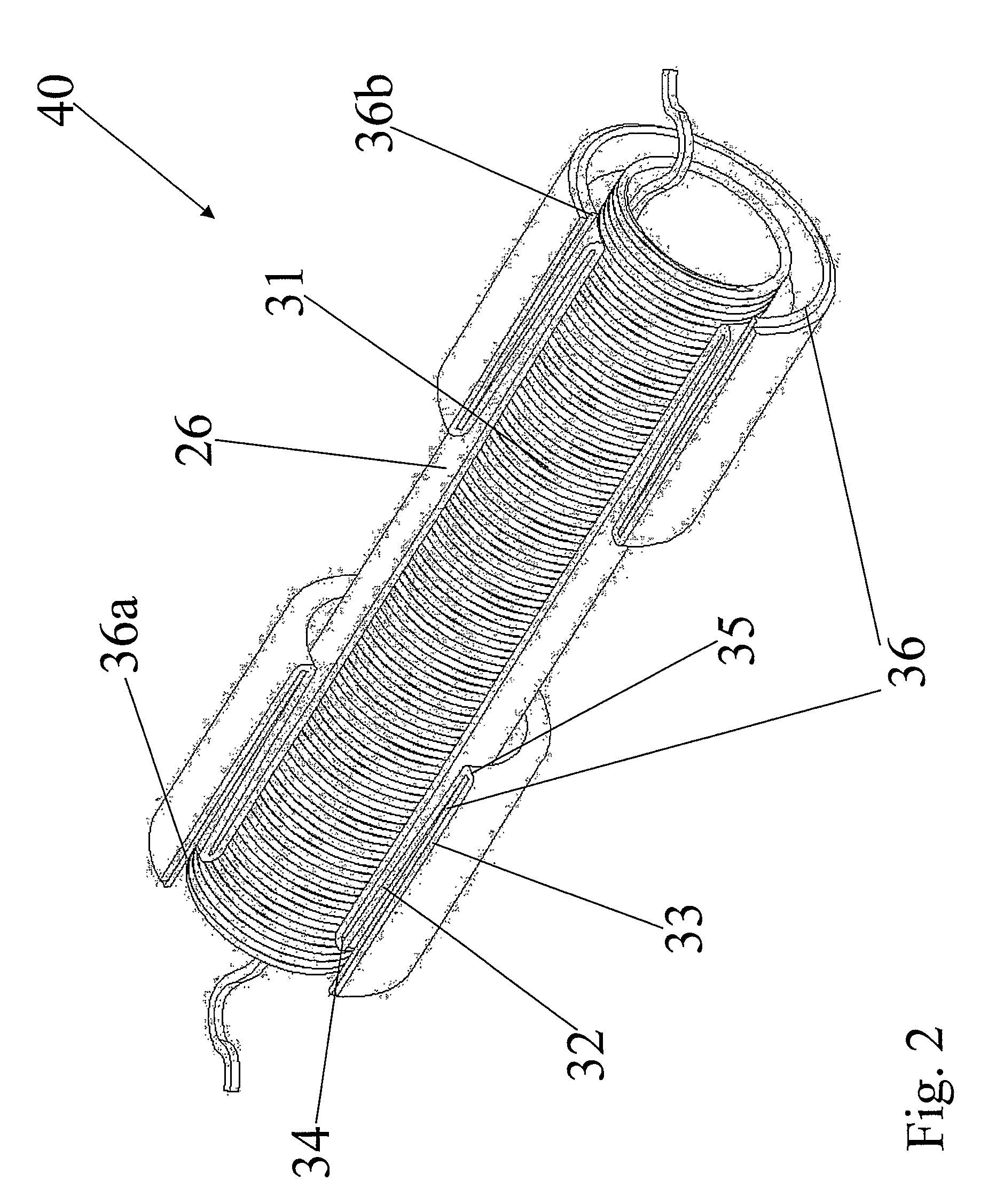
[0176]A tubular elastic sleeve 25—including a semiconductive layer 28, an insulating layer 29 and a high relative dielectric constant layer 30—was supported on a first tubular supporting element 31 of the removable type.

[0177]Said first tubular supporting element 31 was made of polypropylene and was formed of two identical half-supports axially abutting each other.

[0178]A metallic braid 27 was successively provided in the splicing zone to restore the metallic screens 18 of the two cables 11, 12.

[0179]A protective outer sheath 26 was then provided supported—...


PUM


Abstract

The present invention relates to a method for covering an elongate object in particular an electric cable or a pipe. The method includes providing a covering assembly which includes a tubular elastic covering element having at least one end which is folded to define at least one backward folded portion and at least one forward folded portion; a first supporting element which is arranged radially internal to the covering element and which holds the covering element in a radially stretched condition, and a second supporting element which is coaxially arranged around the first supporting element, the second supporting element holding said forward folded portion of the tubular elastic covering element in a radially stretched condition; removing the first supporting element to allow the sleeve to gradually collapse onto the elongate object.

Description

FIELD OF THE INVENTION[0001]The present invention relates to a method for covering an elongate object, such as a pipe, a cable or a cable accessory, e.g. a termination of an electric cable.[0002]In particular, the present invention relates to a method for applying a covering layer to an elongate element, said covering element being in the form of an elastic tubular sleeve.[0003]More in particular, the present invention relates to a method for applying a covering element in correspondence of the splicing zone between two elongate objects.[0004]Even more in particular, the present invention relates to a method for providing a joint between two electric cables, said method comprising the step of providing the splicing zone with a tubular elastic outer sheath having the function of protecting said splicing zone.[0005]Furthermore, the present invention relates to a covering assembly in the form of a pre-expanded elastic tubular sleeve which is provided to an elongate object, for instance...

Claims


Application Information

Patent Timeline
Patent Type & Authority Patents(United States)
IPC IPC(8): H02G15/02H02G15/18
CPCH02G15/1826H02G15/18
Inventor PORTAS, FRANCESCOVALLAURI, UBALDO
Owner PRYSMIAN CAVI E SISTEMI ENERGIA
Why Eureka
Try Eureka