Eureka AIR delivers breakthrough ideas for toughest innovation challenges, trusted by R&D personnel around the world.

Pipelayer and method of loading pipelayer or excavator for transportation

a technology of excavating and pipelayers, applied in the directions of transportation and packaging, mechanical equipment, soil shifting machines/dredgers, etc., can solve the problems of increasing the cost of transportation, pipelayers may idle in the yard, and a substantial period of tim

Inactive Publication Date: 2007-09-27
VOLVO CONSTR EQUIP AB
View PDF37 Cites 36 Cited by
  • Summary
  • Abstract
  • Description
  • Claims
  • Application Information

AI Technical Summary

Benefits of technology

The present invention relates to a pipelayer and a method for loading and transporting it. The method involves raising the pipelayer off track shoes, removing the track assembly from the pipelayer, loading it onto a trailer, and replacing the track assembly on the pipelayer. The invention also includes a pipelayer with a removable counterweight and the ability to operate on steep grades without it. The technical effects of the invention include improved load capacity, better trailer compatibility, and improved performance on steep grades.

Problems solved by technology

When pipelaying duties are complete, the pipelayer may idle in a yard until required again, which may be a substantial period of time.
This increased width causes difficulty in transporting the pipelayer from one work site to another over public roads as the increased width means that the pipelayer will not fit on a standard trailer without requiring permits and / or pilot vehicles which increase the expense associated with transportation.
However, this substantial disassembly of the pipelayer 10 increases the labor and thus also increases transportation costs.

Method used


Image

  • Pipelayer and method of loading pipelayer or excavator for transportation
  • Pipelayer and method of loading pipelayer or excavator for transportation
  • Pipelayer and method of loading pipelayer or excavator for transportation

Examples


Embodiment Construction

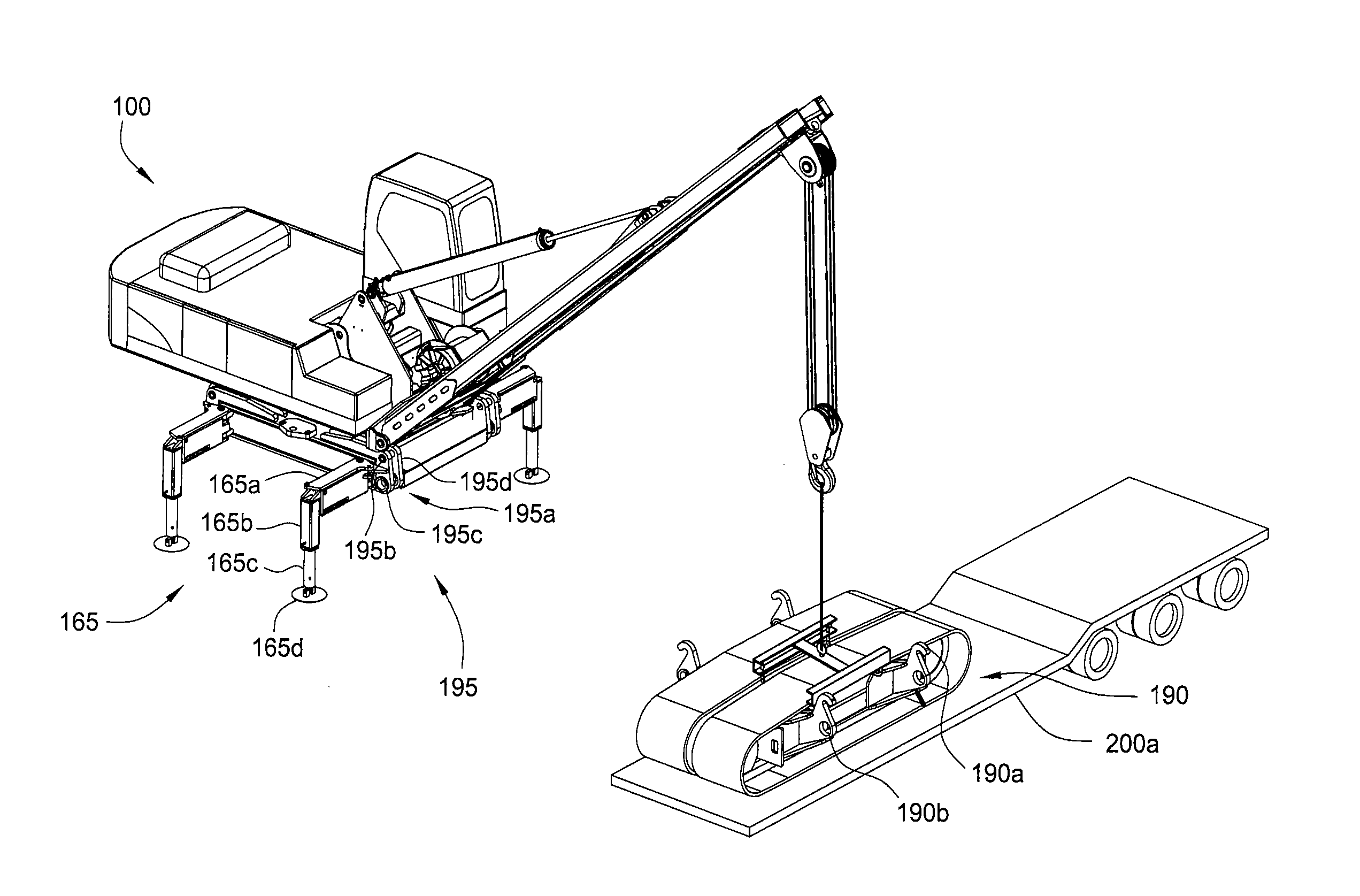
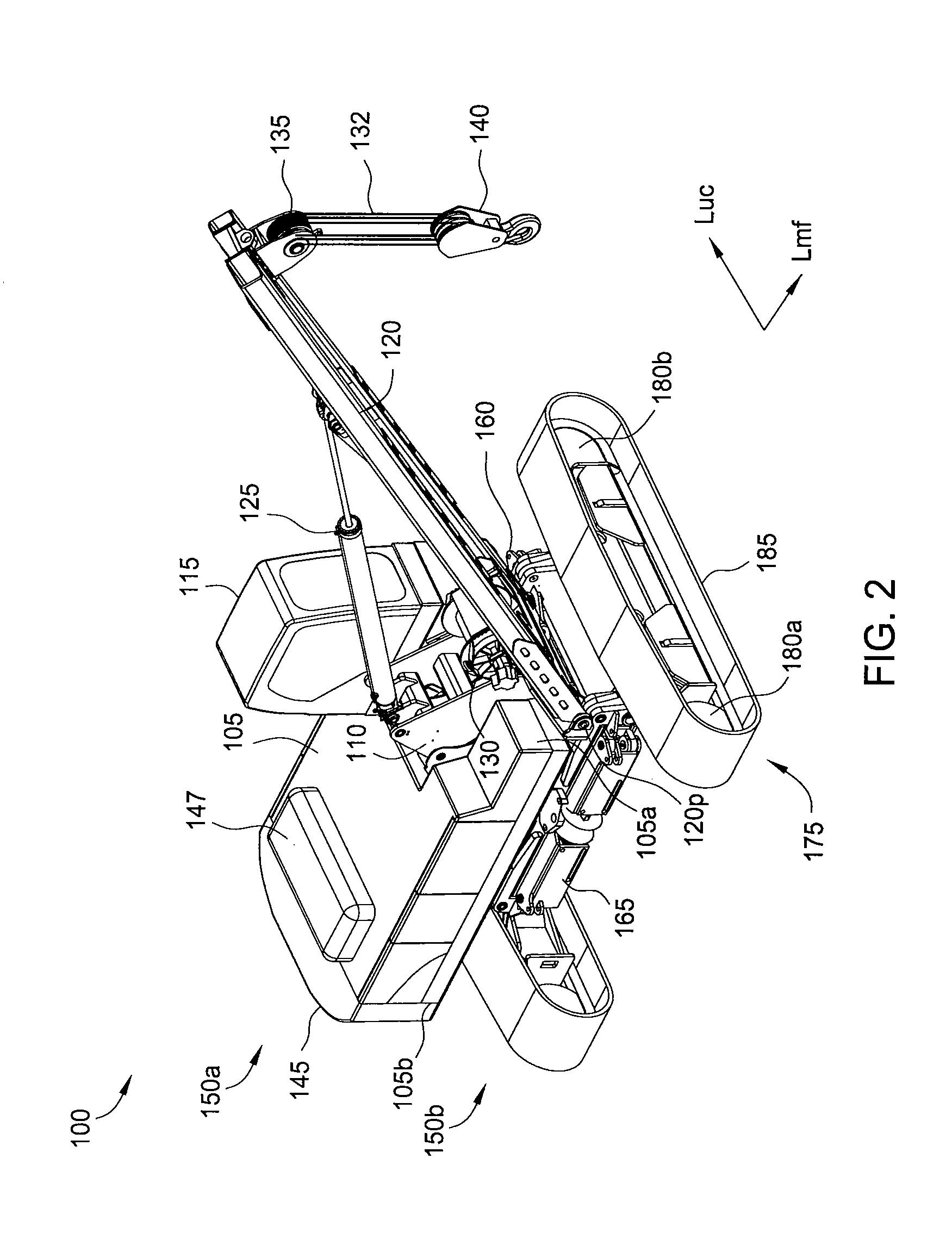
[0041]FIGS. 2-6 are various views of a pipelayer 100, according to one embodiment of the present invention. The pipelayer 100 includes a main assembly 150a mounted on an undercarriage 150b so that the main assembly 150a may rotate relative to the undercarriage 150b. FIG. 2 illustrates a perspective view of the pipelayer 100, wherein a longitudinal axis Lmf of the main assembly 150a is perpendicular to a longitudinal axis Luc of the undercarriage 150b. FIG. 3 illustrates another perspective view of the pipelayer 100, wherein the longitudinal axis Lmf of the main assembly 150a is parallel to a longitudinal axis Luc of the undercarriage 150b. FIG. 4 illustrates another perspective view of the pipelayer 100, wherein the longitudinal axis Lmf of the main assembly 150a is parallel to a longitudinal axis Luc, of the undercarriage 150b. FIG. 5 illustrates an orthogonal view of the pipelayer 100, wherein the longitudinal axis Lmf of the main assembly 150a is perpendicular to a longitudinal a...


PUM


Abstract

Embodiments of the present invention generally relate to a pipelayer and a method for of loading a pipelayer or excavator for transportation. One embodiment includes a method for transporting a pipelayer or excavator from a first work site to a second worksite via a public road. The method includes acts of: raising the pipelayer or excavator off of track shoes of the pipelayer or excavator; removing a first track assembly from the pipelayer or excavator using a boom of the pipelayer or a boom assembly of the excavator; loading the first track assembly onto a first trailer of a first tractor-trailer using the boom of the remaining pipelayer or the boom assembly of the remaining excavator; removing the second track assembly from the pipelayer using the boom of the remaining pipelayer or the boom assembly of the remaining excavator; and loading the second track assembly onto the first trailer using the boom of the remaining pipelayer or the boom assembly of the remaining excavator.

Description

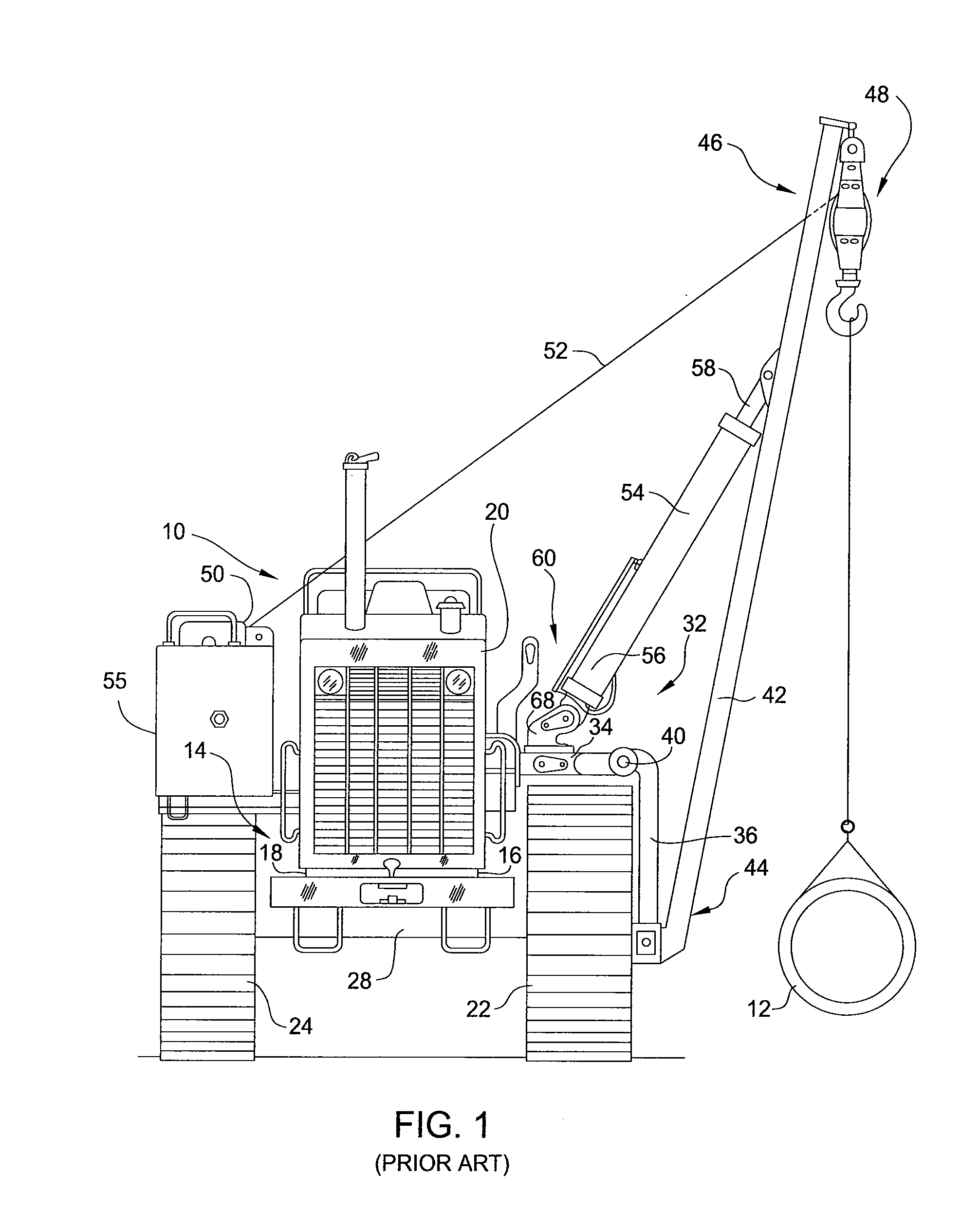
CROSS-REFERENCE TO RELATED APPLICATIONS [0001] This application is a continuation-in-part of U.S. patent application Ser. No. 11 / 125,691, filed May 10, 2005, which is a continuation-in-part (petition pending) of International Application No. PCT / US2003 / 007613, filed Mar. 11, 2003.BACKGROUND OF THE INVENTION [0002] 1. Field of the Invention [0003] Embodiments of the present invention generally relate to a pipelayer and a method for of loading a pipelayer or excavator for transportation. [0004] 2. Description of the Related Art [0005]FIG. 1 is a front view of a prior art pipelayer 10. The pipelayer 10 is typically used for the construction of underground pipelines which transport hydrocarbons, such as natural gas or gasoline. Typical operation of the pipelayer includes raising, carrying, and lowering heavy pipe 12. The pipelayer 10 is a crawler or tractor-type vehicle having a maneuverable boom 42 disposed on a side thereof. For this reason, the pipelayer 10 is referred to as a sidebo...

Claims


Application Information

Patent Timeline
Patent Type & Authority Applications(United States)
IPC IPC(8): B66C9/00
CPCB66C23/36B66C23/365F16L1/06E02F9/003E02F9/18B66C23/44
Inventor DAVIS, DANIEL E.
Owner VOLVO CONSTR EQUIP AB
Why Eureka
Eureka Blog
Learn More