Erecting structure and erecting method for top ring beam construction platform of concrete silo

A construction platform and concrete technology, which is applied in the direction of house structure support, house structure support, house structure support scaffolding, etc., can solve the problems of time-consuming scaffold erection, long silo construction period, and many scaffold materials, etc., and achieve good stability, The effect of shortening the construction period and using less materials

Inactive Publication Date: 2020-01-24
CHINA 19TH METALLURGICAL CORP
View PDF6 Cites 7 Cited by
  • Summary
  • Abstract
  • Description
  • Claims
  • Application Information

AI Technical Summary

Benefits of technology

This invention relates to an improved support system for building platforms that can be easily assembled without requiring much material or tools during assembly process. It also provides stable supports when used alone but requires more space than usual.

Problems solved by technology

In this patented technical problem addressed in this patents are how to construct an effective and efficient way to support rings or other structures inside a concrete silage tank without requiring excessive material during its construction process due to factors like safety regulations.

Method used


Image

  • Erecting structure and erecting method for top ring beam construction platform of concrete silo
  • Erecting structure and erecting method for top ring beam construction platform of concrete silo
  • Erecting structure and erecting method for top ring beam construction platform of concrete silo

Examples


Embodiment Construction

[0025] The present invention will be further described below in conjunction with the accompanying drawings and embodiments.

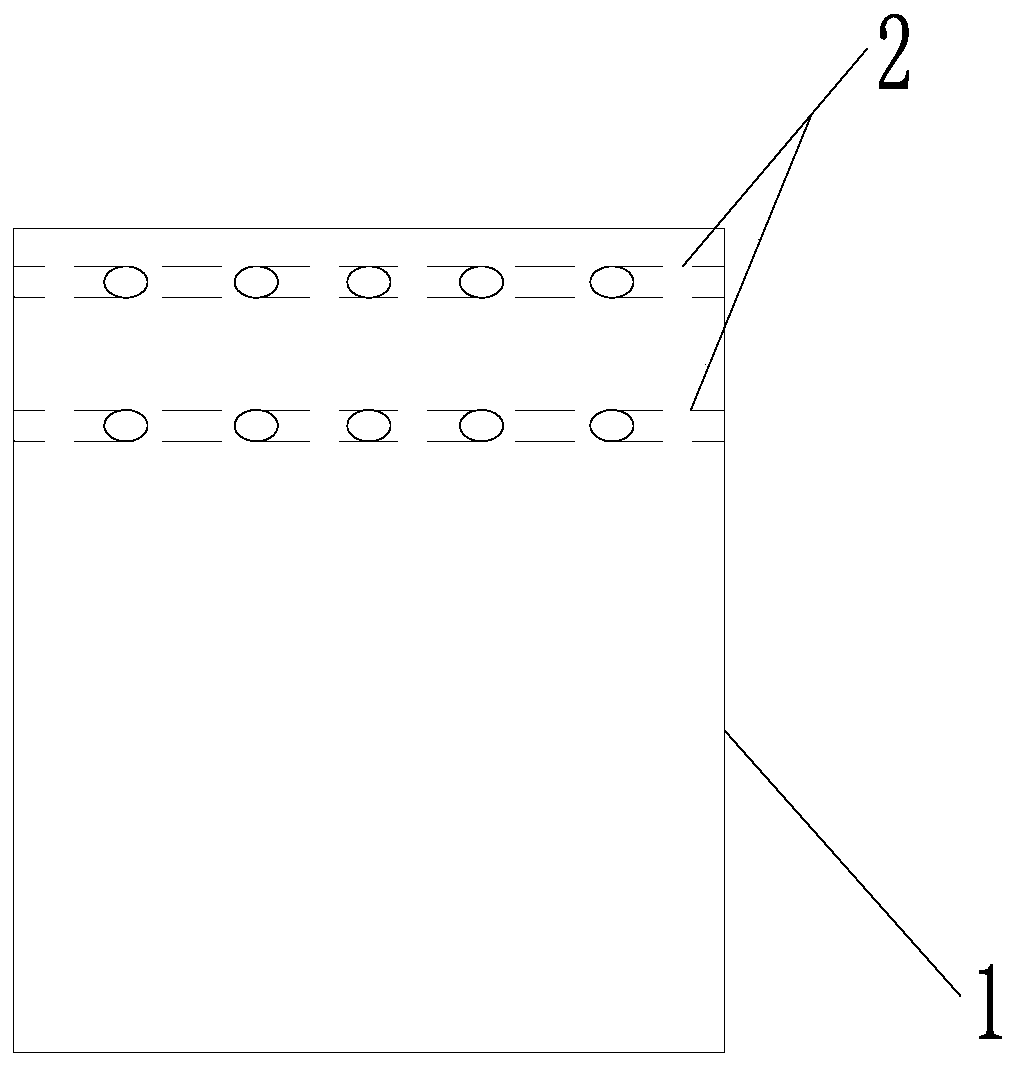
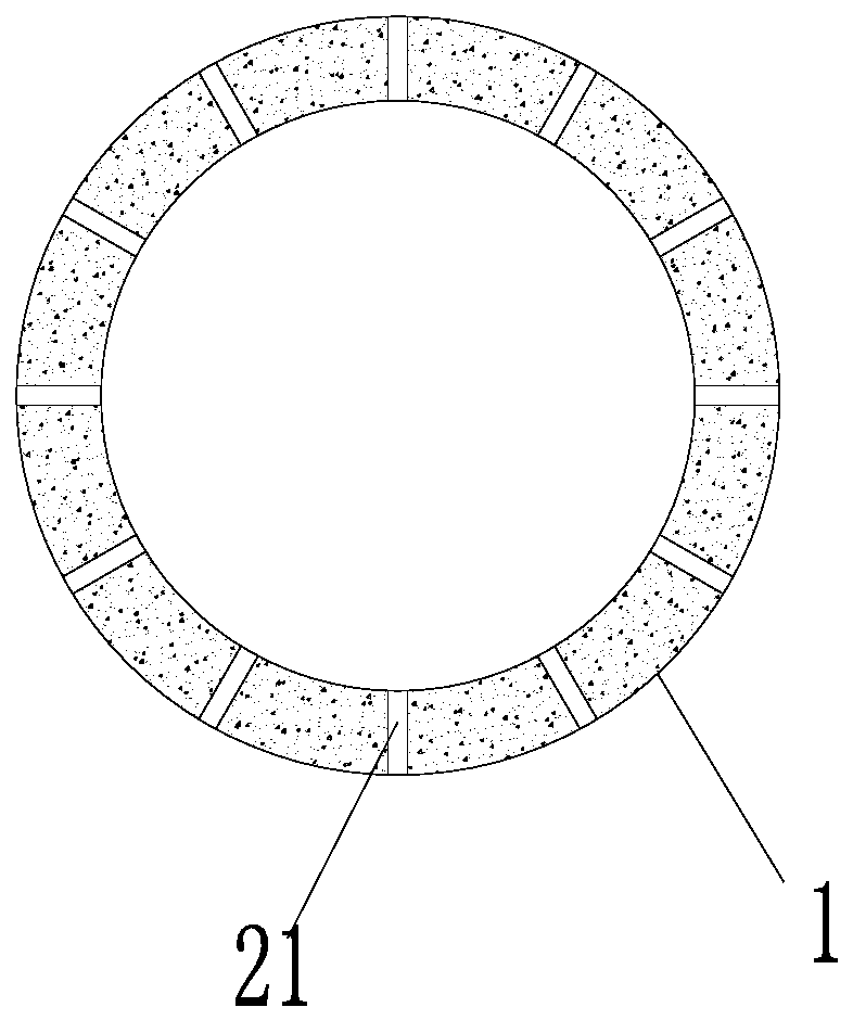
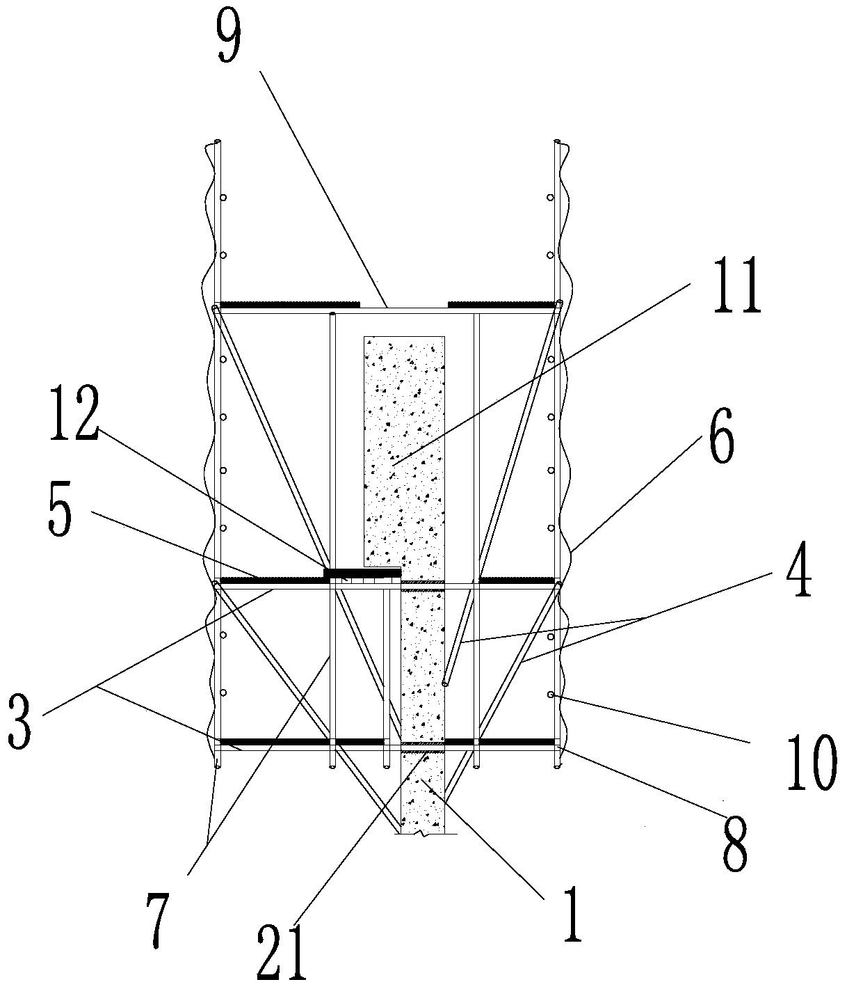
[0026] Such as Figure 1 to Figure 3 As shown, the erection structure of the ring beam construction platform at the top of the concrete silo of the present invention includes: a cantilevered scaffold pipe 3 and a steel pipe layer 2 composed of a plurality of horizontally arranged steel pipes 21 embedded in the upper end of the cylinder wall 1; the steel pipe layer 2 There are two layers, and there is a space between the two layers. The steel pipes 21 of the steel pipe layer 2 in each layer pass through the cylinder wall 1 and are distributed along the circumference of the cylinder wall 1, and the steel pipes 21 of the steel pipe layer 2 in each layer Set at intervals; the cantilevered scaffold pipe 3 is inserted into the steel pipe 21 of the steel pipe layer 2 and both ends are suspended in the air; the erection structure also includes a vertical pole s...


PUM

PropertyMeasurementUnit
Thicknessaaaaaaaaaa
Plate thicknessaaaaaaaaaa
Board widthaaaaaaaaaa

Abstract

The invention provides a low-material-consumption and simple-structure erecting structure and erecting method for a top ring beam construction platform of a concrete silo and relates to the technicalfield of concrete silo construction. The erecting method for the top ring beam construction platform of the concrete silo comprises the following steps: pre-burying two layers of steel pipe layers separately consisting of a plurality of horizontally arranged steel pipes at the upper end of a silo wall, putting cantilever scaffold pipes into the steel pipes of the steel pipe layers, and separatelyerecting vertical rod scaffold pipes, cross rod scaffold pipes and diagonal scaffold pipes for support stress components at the cantilever sections, located at the two sides of the silo wall, of the cantilever scaffold pipes. The construction cost can be saved, and the construction cycle can be shortened.

Description


Claims


Application Information

Patent Timeline
Owner CHINA 19TH METALLURGICAL CORP
Why Eureka
Try Eureka