Lifting Device

a lifting device and lifting frame technology, applied in the direction of lifting devices, lifting frames, etc., can solve the problems of large installation space, excessive control, and large design investment of known structures, and achieve the effect of less maintenan

Inactive Publication Date: 2007-09-27
SIEMENS AG
View PDF4 Cites 15 Cited by
  • Summary
  • Abstract
  • Description
  • Claims
  • Application Information

AI Technical Summary

Benefits of technology

[0011] In another embodiment, the drive unit has a spindle and a motor. A spindle and a motor have relatively less maintenance than a hydraulic cylinder. In one embodiment, a vertically running spindle is driven, via a corresponding gear mechanism, by an electric motor with its axis of rotation perpendicular to the spindle axis. This embodiment allows a space-saving construction of the lifting device.

Problems solved by technology

The known structures require a large amount of installation space.
The known solutions, for example, are too large, involve too much design outlay and require excessively complicated controls.

Method used


Image

  • Lifting Device
  • Lifting Device
  • Lifting Device

Examples


Embodiment Construction

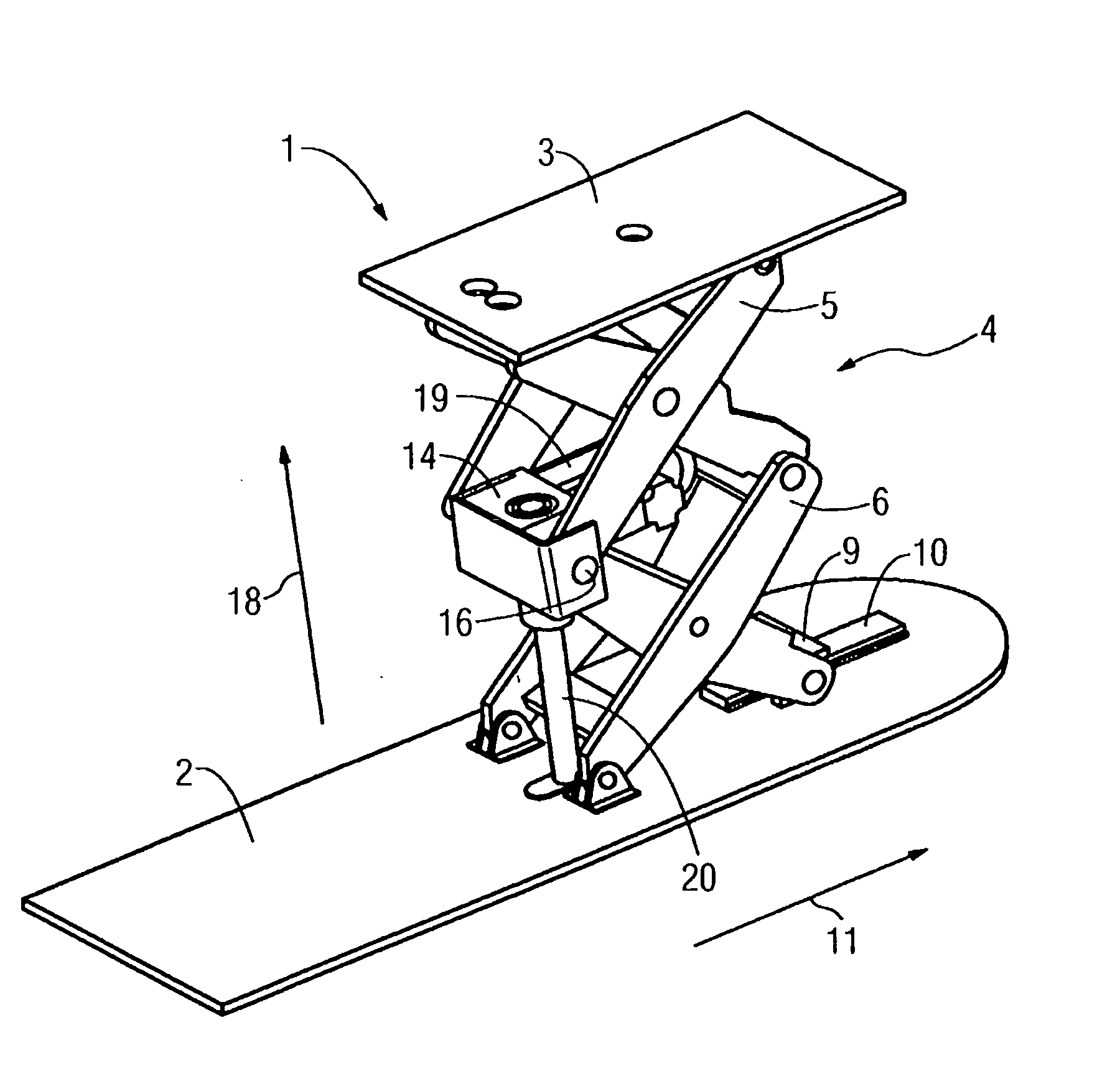
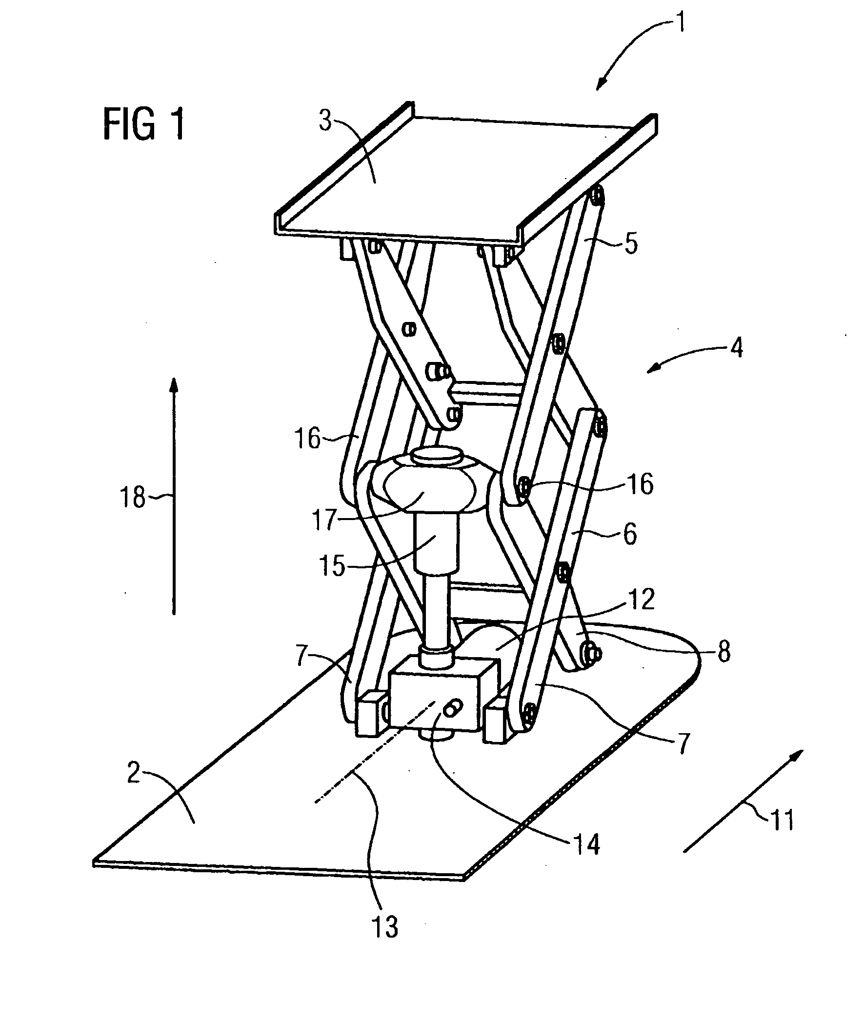
[0018] In one embodiment, as shown in FIG. 1, a lifting device 1 includes a bottom part, in the form of a base plate 2, a top part, in the form of a patient support 3, and a lifting linkage. The lifting linkage is configured as a double scissors mechanism or double scissors structure 4. The double scissors structure 4 comprises, for example, two scissors assemblies 5, 6 as sub-linkages, which are connected to one another by a central articulation (joint) 16.

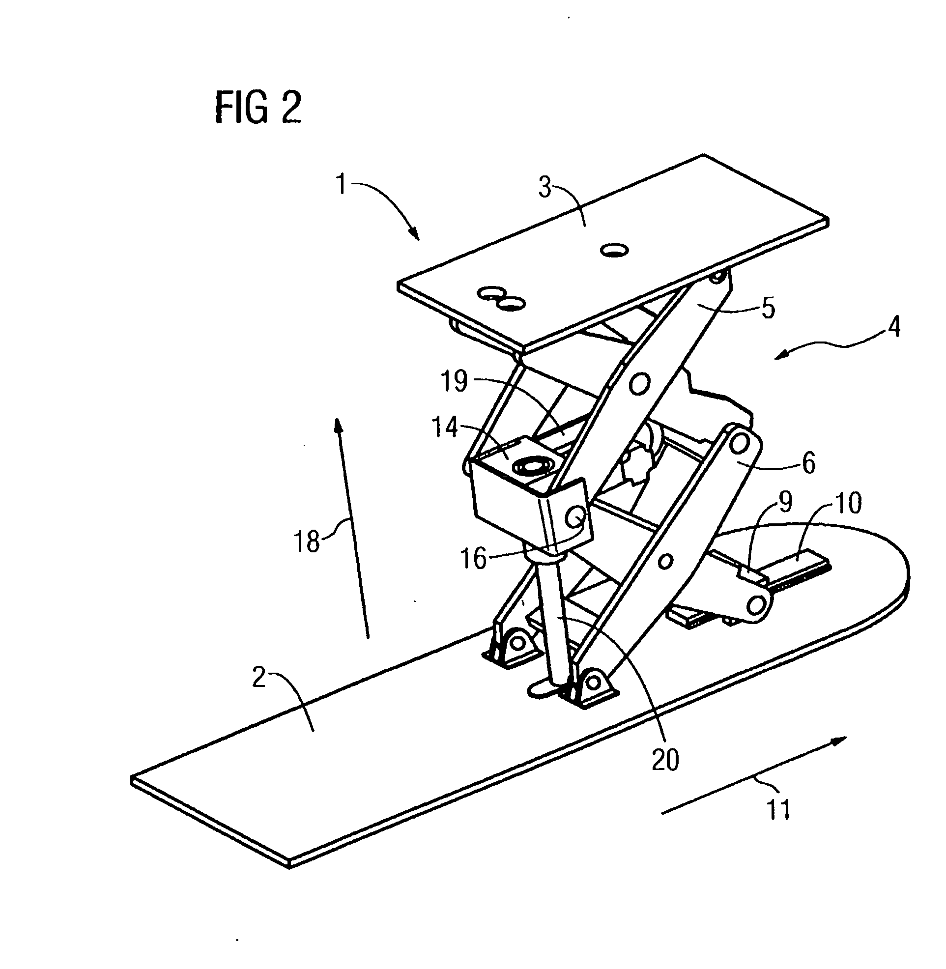
[0019] The bottom scissors assembly 6 is supported by the base plate 2. The bottom scissors assembly 6 includes front scissor feet 7 and rear scissor feet 8. The front scissor feet 7 are connected to the base plate 2. As shown in FIG. 2, the rear scissors feet 8 of the bottom scissors assembly 6 are connected to one another via a slide 9. For example, when the double scissors structure 4 is opened and closed, the slide runs back and forth in the running direction 11 on a running rail 10 fastened on the base plate 2.

[0020] In on...


PUM


Abstract

A lifting device is provided. The lifting device includes a top part and a bottom part. A lifting linkage connects the top part to the bottom part and has at least two sub-linkages connected to one another via a central articulation. A drive unit is operable to adjust the height of the top part and act on the central articulation.

Description

[0001] The present patent document is a continuation of PCT Application Serial Number PCT / EP2005 / 051223, filed Mar. 16, 2005, designating the United States, which is hereby incorporated by reference.BACKGROUND [0002] 1. Field [0003] The present embodiments relate to a lifting device. [0004] 2. Related Art [0005] Lifting devices are generally known from the prior art. For example, WO 98 / 46137 discloses a lifting device that adjusts the height of a patient support. Parallelogram structures are used as lifting linkages. The known structures require a large amount of installation space. Large lifting forces are necessary for height adjustment. These lifting forces are not constant. Different displacement speeds arise during height adjustment. The known solutions, for example, are too large, involve too much design outlay and require excessively complicated controls. SUMMARY [0006] In one embodiment, a lifting device includes a top part and a bottom part. A lifting linkage connects the t...

Claims


Application Information

Patent Timeline
Patent Type & Authority Applications(United States)
IPC IPC(8): B66F3/00B66F7/06
CPCB66F7/0666
Inventor PIEGER, KONRADWEIDNER, PAUL
Owner SIEMENS AG
Why Eureka
Try Eureka