No dead time data acquisition

a data acquisition and dead time technology, applied in the field of data acquisition, can solve the problems of rare incorrect operation, missed waveforms that show the incorrect operation of the circuit, and dead tim

Inactive Publication Date: 2007-09-27
TEKTRONIX INC
View PDF18 Cites 21 Cited by
  • Summary
  • Abstract
  • Description
  • Claims
  • Application Information

AI Technical Summary

Benefits of technology

[0005] The objects, advantages and other novel features of the present invention are apparent from the following detailed description when read in conjunction with the appended claims and attached drawing.

Problems solved by technology

In a digital oscilloscope dead time often occurs when the instrument is busy with a number of tasks, i.e., not able to process a trigger when a previously acquired waveform is being read from an acquisition memory or when it is busy drawing the acquired data to make an image of the waveform for display.
The incorrect operation may be rare, perhaps occurring once in thousands of correct cycles of operation.
The waveforms that show the incorrect operation of the circuit may be missed, i.e., may not be acquired.
An oscilloscope user may have to wait a long time in order to view the incorrect operation.
Even though incorrect circuit operation may not be visible, the oscilloscope user may not ever have confidence that the circuit is working properly since only a small fraction of the waveforms are drawn on the oscilloscope display.

Method used


Image

  • No dead time data acquisition
  • No dead time data acquisition
  • No dead time data acquisition

Examples


Embodiment Construction

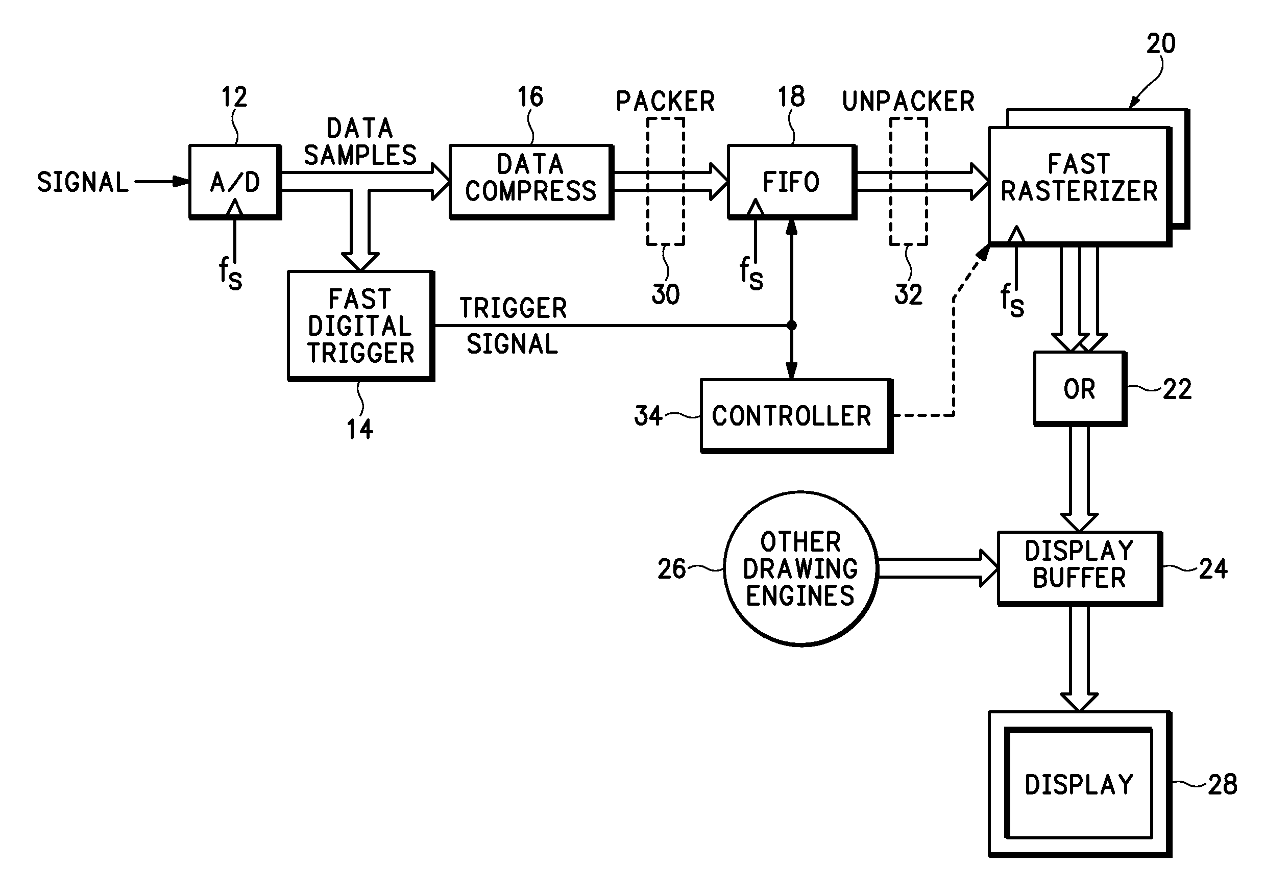
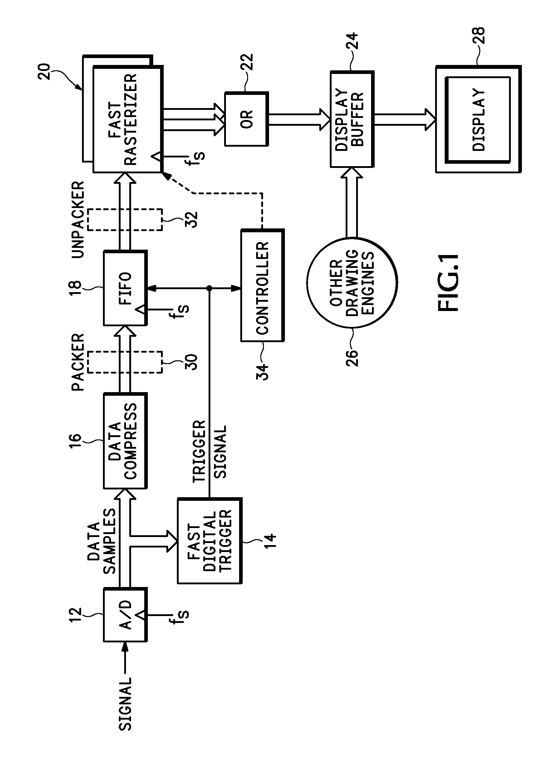
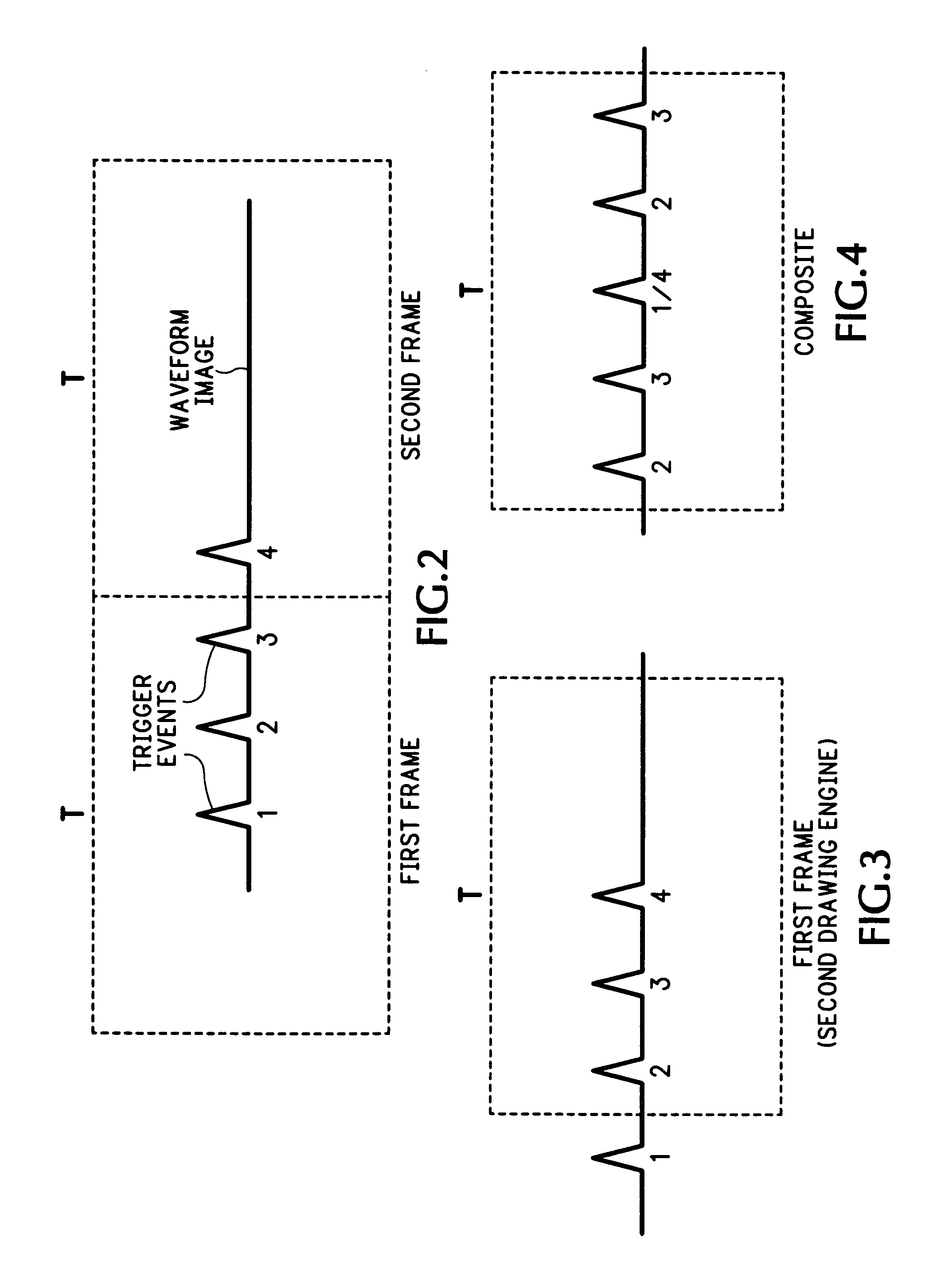
[0010] Referring now to FIG. 1 a digital data acquisition architecture for a measurement instrument, such as a digital oscilloscope, is shown that allows every valid trigger event to be displayed. There are four requirements to make “no dead time” possible, which are described below. By definition “no dead time” means all trigger events are shown on a display screen, every waveform image associated with the trigger events has a trigger event at a specified trigger location T on the display screen, and it is not necessary (or desirable) to display all trigger events at the specified trigger location.

[0011] Every trigger event must be detected, even when trigger events arrive at the full bandwidth of the measurement instrument, so fast trigger recognition is required. In addition to recognizing each trigger event, the time of each trigger event relative to the acquired data must be computed. Therefore the signal being monitored is converted by an analog-to-digital converter (ADC) 12 ...


PUM


Abstract

A “no dead time” data acquisition system for a measurement instrument receives a digitized signal representing an electrical signal being monitored and generates from the digitized signal a trigger signal using a fast digital trigger circuit, the trigger signal including all trigger events within the digitized signal. The digitized signal is compressed as desired and delayed by a first-in, first-out (FIFO) buffer for a period of time to assure a predetermined amount of data prior to a first trigger event in the trigger signal. The delayed digitized signal is delivered to a fast rasterizer or drawing engine upon the occurrence of the first trigger event to generate a waveform image. The waveform image is then provided to a display buffer for combination with prior waveforms and / or other graphic inputs from other drawing engines. The contents of the display buffer are provided to a display at a display update rate to show a composite of all waveform images representing the electrical signal.

Description

BACKGROUND OF THE INVENTION [0001] The current invention relates to data acquisition, and more particularly to “no dead time” data acquisition for measurement instruments, such as oscilloscopes. [0002] The “dead time” of a measurement instrument, such as an oscilloscope, is a time when data acquisition circuitry does not respond to a valid trigger event by displaying a waveform representing an electrical signal being monitored. In an analog oscilloscope, for example, dead time occurs during beam retrace time on a cathode ray tube. In a digital oscilloscope dead time often occurs when the instrument is busy with a number of tasks, i.e., not able to process a trigger when a previously acquired waveform is being read from an acquisition memory or when it is busy drawing the acquired data to make an image of the waveform for display. Electronic circuits occasionally work in an unexpected manner. The incorrect operation may be rare, perhaps occurring once in thousands of correct cycles o...

Claims


Application Information

Patent Timeline
Patent Type & Authority Applications(United States)
IPC IPC(8): G01R13/14
CPCG01R13/0254
Inventor SULLIVAN, STEVEN K.BEALE, TERRANCE R.VEITH, KRISTIE
Owner TEKTRONIX INC
Why Eureka
Try Eureka