Line powering in a multi-line environment

a multi-line environment and line power technology, applied in circuit-breaking switches, circuit-breaking switches, electrical equipment, etc., can solve the problems of reducing the service life of the cable,

Inactive Publication Date: 2007-09-27
POSITRON ACCESS SOLUTIONS
View PDF16 Cites 85 Cited by
  • Summary
  • Abstract
  • Description
  • Claims
  • Application Information

AI Technical Summary

Problems solved by technology

The remote terminal, however, may not be near a power source, or the available power source may already be supplying power at capacity to other devices.
Pulling addition cabling and connecting power, if possible, may be difficult and expensive.
Likewise, power is an expensive resource which is usually metered to a particular user.
In a shared equipment room containing a remote terminal, shared power usage may create metering complexities or providing power may unfairly burden certain parties.
In addition, disruptions to the power supplied to a remote location will likewise disrupt exchange of data between the two communication systems if the remote communication device is dependant on power at the remote location.
Often the communication link carries important business, safety, or personal data and disruption of the communication link is highly undesirable.
While the central office may be battery backed, the remote terminal may not have such a luxury and hence, a disruption of power at the remote location, where the remote terminal is located, would disrupt data exchange.
Prior art systems that utilize line powering suffer from numerous drawbacks.
One such drawback is that prior art systems, when configured as multi-line communication systems, simply duplicate a single line powering circuit for each line.
This is undesirably expensive as the same line powering hardware and functionality is repeated for each line thereby leading to a duplication of equipment and increased power consumption.
Another drawback arises due to the inflexibility of prior art systems when dealing with difficulty on a particular line.
For example, in a prior art system having five powered lines, when any one of those five lines does not supply sufficient power, the entire remote terminal will likewise become inoperable because insufficient power is flowing to the remote device.
As can be appreciated, this scenario is undesirable because system operation is dependent on all five lines supplying adequate power.
In addition, the primary communication device may detect a degradation that is not at a level of severity as a fault or failure.
In that case, the device may alert the user or management entity to a potential future failure, but not take autonomous action.

Method used


Image

  • Line powering in a multi-line environment
  • Line powering in a multi-line environment
  • Line powering in a multi-line environment

Examples


Embodiment Construction

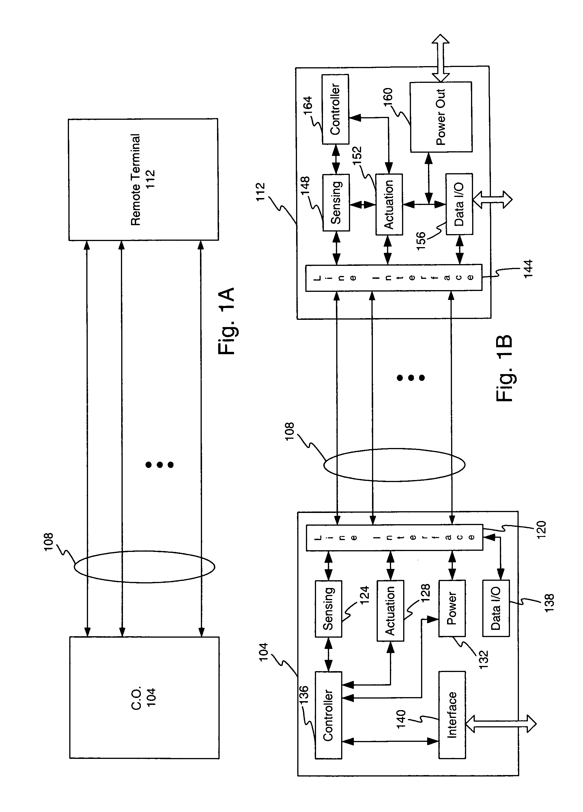
[0037]FIG. 1A illustrates an example embodiment of a multi-line point to point communication system. As shown, a central office (CO) device 104 communicates via two or more lines 108 with a remote terminal 112. As used herein, the channel collectively comprises two or more lines. The two or more lines 108 may comprise any type of communication path. The CO device 104 and remote terminal 112 utilized the two or more lines 108 to improve data transfer efficiency. In this embodiment, it is contemplated that the CO device 104 may supply power to the remote terminal 112 via the two or more lines 108 to thereby form a line powered communication system.

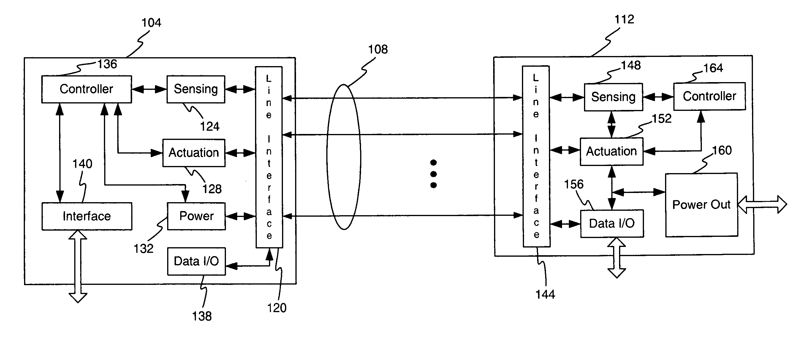
[0038]FIG. 1B illustrates a block diagram of an example embodiment of a line powered, multi-line point to point communication system. In this example embodiment, a CO device 104 connects to the lines 108 via a line interface 120. Within the CO device 104, the line interface 120 may comprise one or more switches, not shown. In turn, the line...


PUM


Abstract

A line powering system for a multi-channel communication system is disclosed having a central office or primary communication terminal configured to communicate with one or more remote locations via two or more communication lines. Line powering, from the primary location to the remote location, is provided by a power supply, which is selectively connected to one or more of the lines via a switching module. Line monitoring and switch control may occur automatically or by a controller. A ground fault detector is provided to monitor for excessive ground fault current and selectively disconnect the faulted line. A rapid line voltage discharge module is provided to discharge line voltage to meet specification.

Description

FIELD OF THE INVENTION [0001] The invention relates to line powering remote communication devices and in particular to a method and apparatus for line powering remote terminals in a multi-line point to point communication system or multi-line point to multi-point communication system. RELATED ART [0002] Many communication systems have been developed and implemented to exchange data between remote locations. The locations, at which the communication devices are placed, are often connected by a communication channel capable of conveying the data between each location. The locations may comprise any type locations such as a central office, office building equipment room, repeater stations, cellular telephone base station, or individual office. [0003] As can be appreciated, the communication devices require power, in the form of electricity, to achieve operation of the communication systems. Hence, power must be provided to the communication device locations. In the example environment ...

Claims


Application Information

Patent Timeline
Patent Type & Authority Applications(United States)
IPC IPC(8): H01H73/00
CPCH04M3/18
Inventor ITRI, BENEDICT A.SMITH, CHRISTOPHER S.
Owner POSITRON ACCESS SOLUTIONS
Why Eureka
Try Eureka