Tooth orthopedic appliance

Inactive Publication Date: 2007-09-27
LIN FU YI
View PDF5 Cites 6 Cited by
  • Summary
  • Abstract
  • Description
  • Claims
  • Application Information

AI Technical Summary

Benefits of technology

[0009] The slanting extensions of the side wing portions can be utilized as a guide for bending a holding wire along both sides of the wire holding slot and directing toward a direction of the main wire trench in such that the holding

Problems solved by technology

Therefore, the connection between edgewise bracket 10 and the correcting wire 5 is poor that results t

Method used


Image

  • Tooth orthopedic appliance
  • Tooth orthopedic appliance
  • Tooth orthopedic appliance

Examples


Embodiment Construction

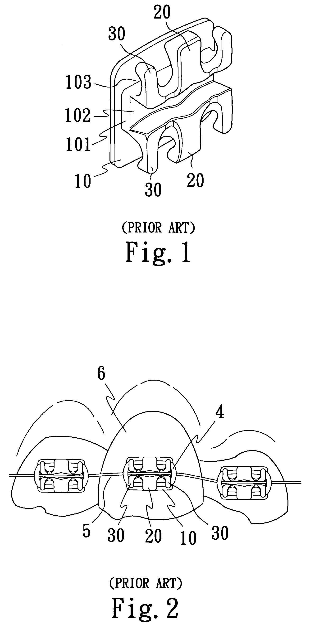
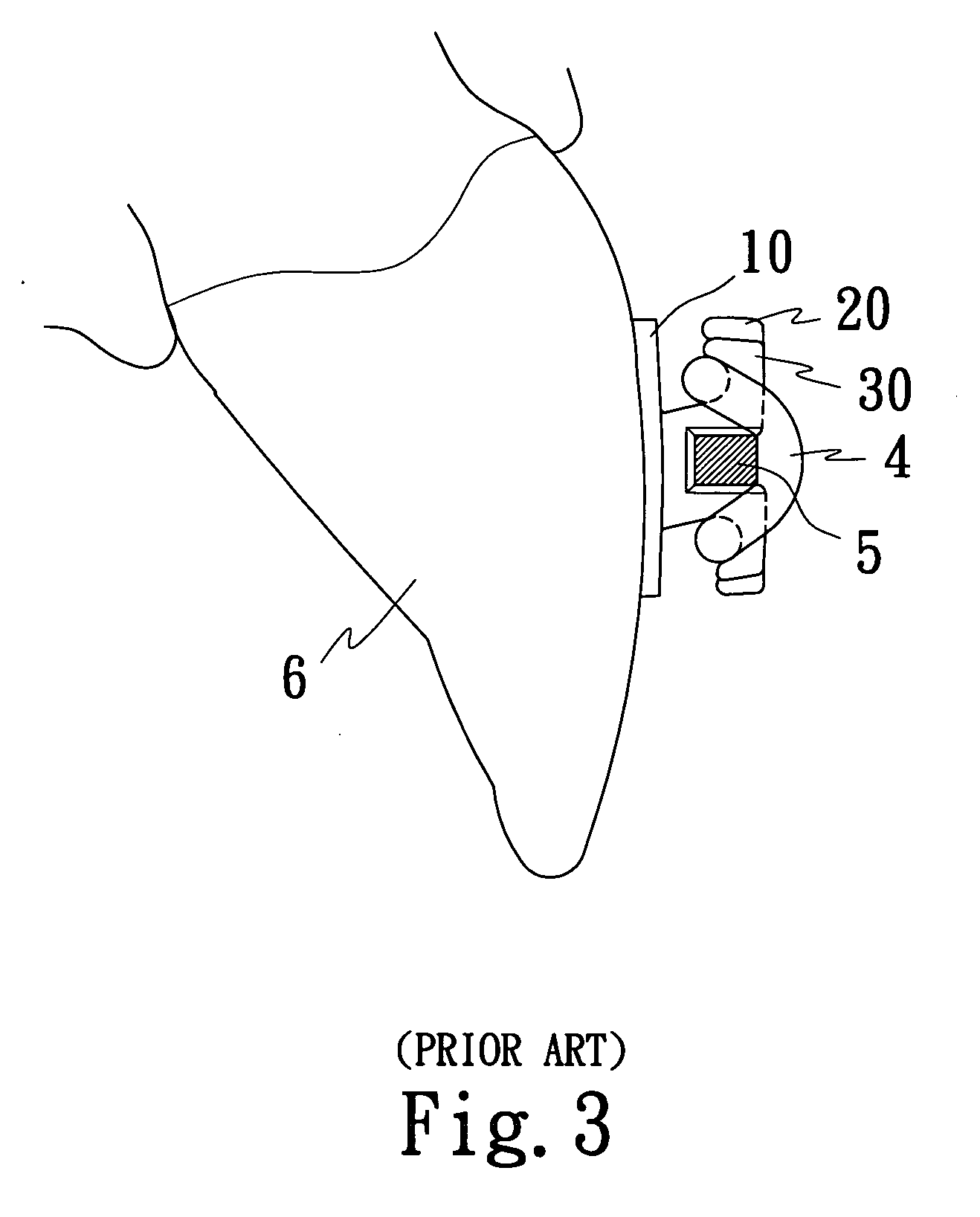
[0031]FIGS. 1-3 show the conventional tooth orthopedic appliance with a defected structural design resulting low efficiency.

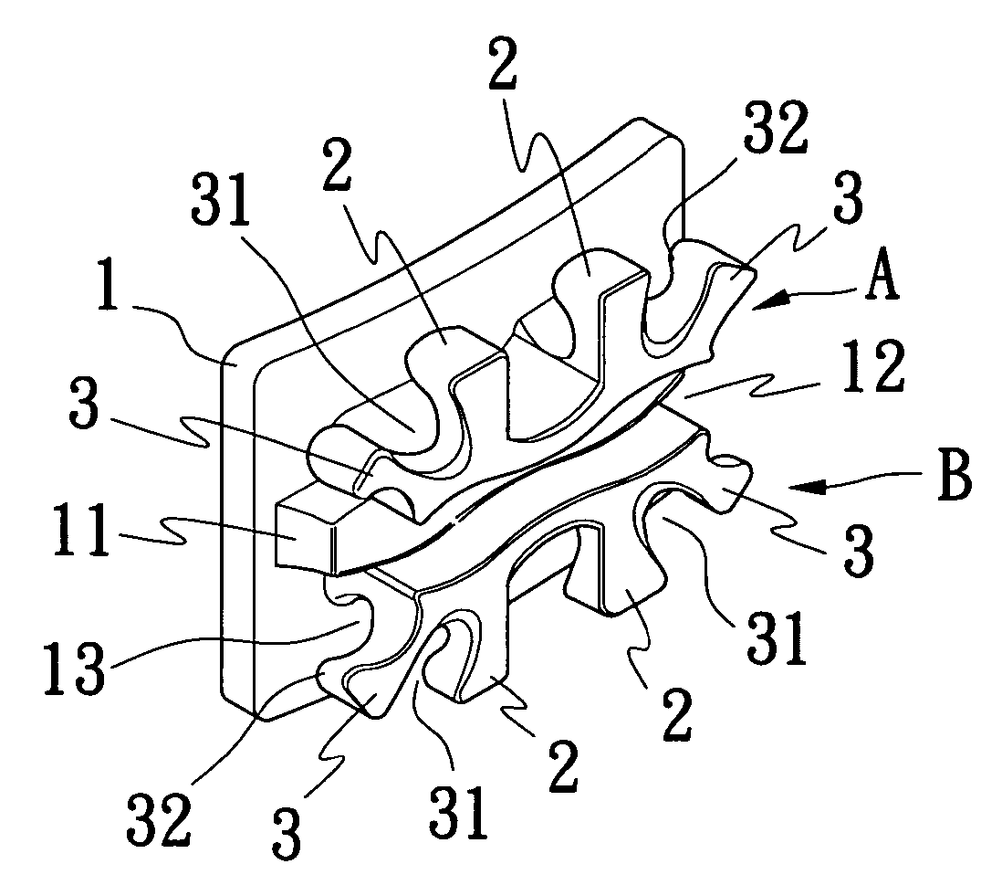
[0032]FIG. 4 is a 3-D view of an improved structure of a tooth orthopedic appliance of a first preferred example of the present invention. FIGS. 5 and 6 are diagrams showing 2-D front and side views of an improved structure of a tooth orthopedic appliance of the first preferred example of the present invention. The improved tooth orthopedic appliance of the present invention comprises a bracket 1, a middle supporting portion 2 and a side wing portion 3. A base 11 is provided at a middle part of the bracket 1. Two protruding portions A and B are formed respectively and correspondingly on each side of the base 11.

[0033] A main wire trench 12 is formed and defined by the sidewalls of the two protruding portions A and B. A plurality of middle supporting portions 2, which are located and extended respectively on the two protruding portions A and B are parallel to ...


PUM


Abstract

A tooth orthopedic appliance has a bracket, a plurality of middle supporting portions and a plurality of side wing portions. The bracket is connected to a surface of the tooth, wherein a base is provided on a middle part of the bracket. A main wire trench is utilized to locate a correcting wire. The plurality of middle supporting portions are located respectively at a middle part of two protruding portions of the bracket, wherein the middle supporting portions are parallel to the bracket and perpendicular to the main wire trench. A wire holding slot is formed in between the bracket and every middle supporting portion for hooking a holding wire. A notch is defined by sidewalls of the middle supporting portions and the side wing portions in order to locate the holding wire for locking a top portion of the correcting wire such that an unfastened condition is formed.

Description

BACKGROUND OF THE INVENTION [0001] 1. Field of Invention [0002] The present invention relates generally to an improved structure of a tooth orthopedic appliance. More particularly, the present invention relates to an improved supporting structure of an orthopedic appliance that can be used to support, align, or hold the teeth in a correct position. [0003] 2. Description of the related Art [0004] The convectional supporting structure of an orthopedic appliance such as, the appliance “Edgewise orthodontic bracket” disclosed in U.S. Pat. No. 5,470,228 shown in FIG. 1. The edgewise orthodontic bracket comprises a base 101 located on a middle portion of an edgewise bracket 10. Two corresponding protrusions are formed on a top part of the base 101, wherein a central leg portion 20 is provided on a central part of the two protrusions. Wing tip portions 30 are formed respectively on each of the mesial and distal sides of the central leg portion 20 such that a T-shaped structure is formed. A...

Claims


Application Information

Patent Timeline
IPC IPC(8): A61C3/00
CPCA61C7/30A61C7/14
Inventor LIN, FU-YI
Owner LIN FU YI
Why Eureka
Try Eureka