
Vision catheter having electromechanical navigation

a technology of electromechanical navigation and vision catheter, which is applied in the field of medical devices, can solve the problems of complex and limited bronchial branch complexity, and the current navigation system is limited, and the conventional bronchoscope cannot reach the third or fourth bifurcation level of the bronchial tree, so as to improve the accuracy of endoscopic exploration of the periphery of the lung

Inactive Publication Date: 2007-09-27
BOSTON SCI SCIMED INC
View PDF21 Cites 126 Cited by
  • Summary
  • Abstract
  • Description
  • Claims
  • Application Information

AI Technical Summary

Benefits of technology

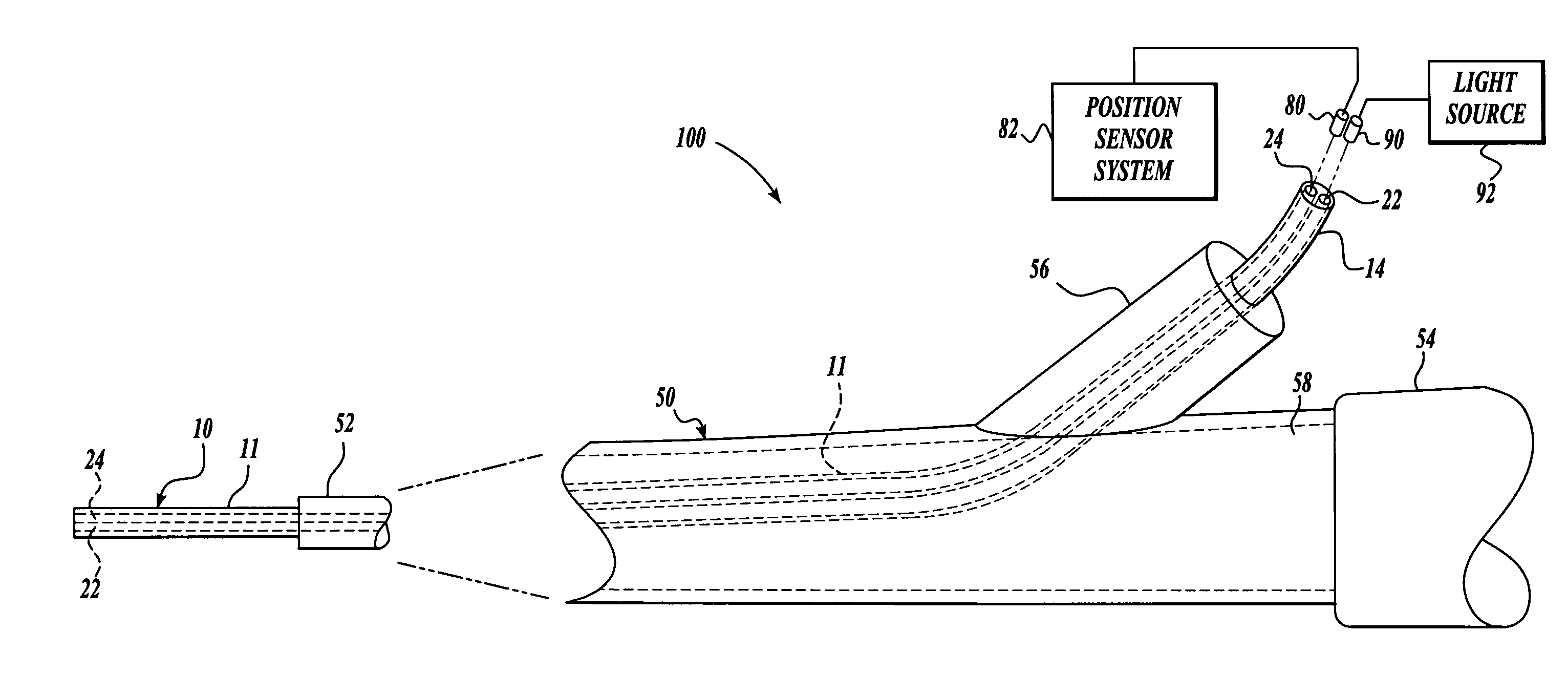
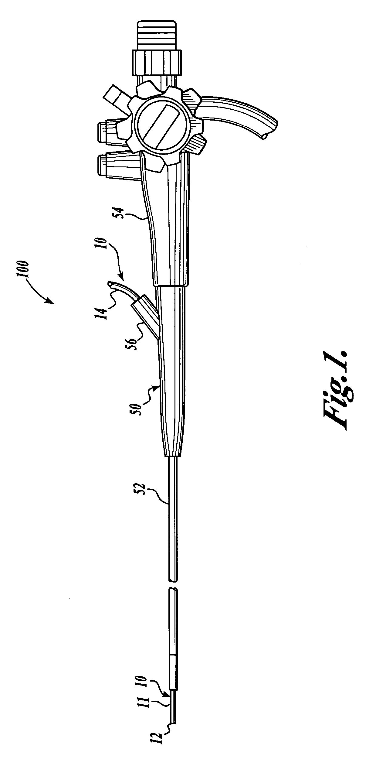
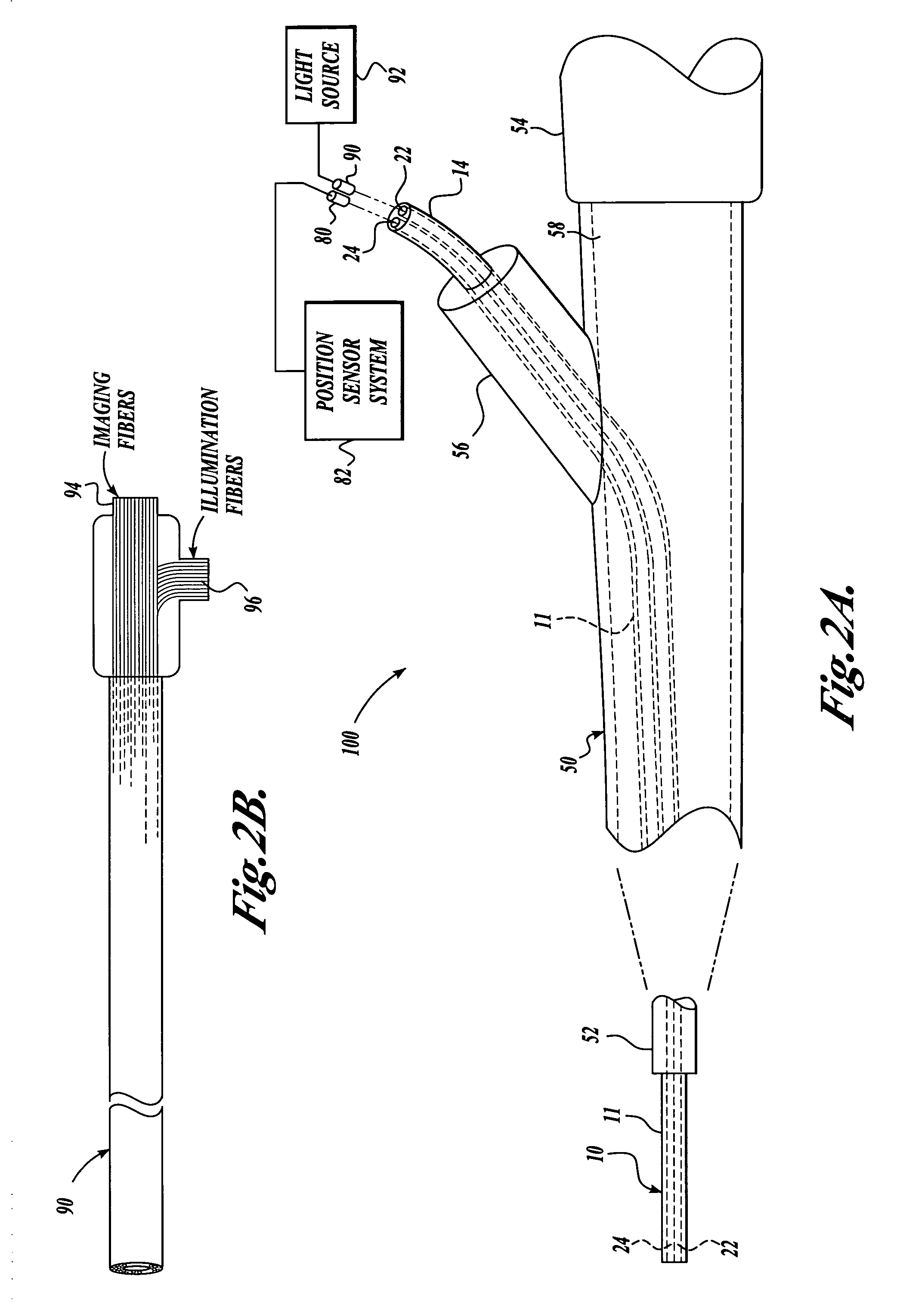
[0006] To address these and other concerns, the present invention is a visualization system including a small gauge vision catheter having an imaging channel for imaging means and a separate working channel. An electromagnetic sensor element is included in the vision catheter to provide position tracking. In one embodiment, the position sensor is removably positioned in the working channel. The working channel also provides access for therapeutic and diagnostic tools. In some embodiments, the vision catheter may have a shaft with a maximum outer diameter of less than about 3.0 mm and is capable of insertion through an instrument channel of a bronchoscope. In other embodiments, the vision catheter may have a shaft with a maximum outer diameter of about 4.2 mm that includes an outer layer with a braided structure that may be directly inserted into a living body.

Problems solved by technology

As a consequence, a conventional bronchoscope can only reach about the third or fourth bifurcation level of the bronchial tree.
Another factor that complicates endoscopic exploration of the periphery of the lung is the complexity and number of bronchial branches that exist.
The current navigation systems are limited, however, by the lack of means for directly visualizing the patient's anatomy at the distal location of the extended working channel.
This lack of direct visualization may result in inaccurate initial targeting of a therapeutic site, such as a biopsy site, without any indication of whether the correct target tissue has been reached, due in part to tolerance issues on how accurate these systems can be.

Method used


Image

  • Vision catheter having electromechanical navigation
  • Vision catheter having electromechanical navigation
  • Vision catheter having electromechanical navigation

Examples


Embodiment Construction

[0018] In traditional pulmonary endoscope systems, such as bronchoscopes, electromagnetic sensors have been developed that allow the guided delivery of catheters (often referred to as extended working channels) to target locations in the bronchi and peripheral airways of a patient. In operation, an electromagnetic sensor is fed through a single lumen of a catheter. The location of the sensor element is mapped, and the sensor element is removed from the lumen. An instrument is then inserted into the lumen for therapeutic intervention. However, as discussed above, the extended working channel / sensor systems do not provide direct imaging capability.

[0019] To address these and other problems, the present invention is a visualization system that includes a small gauge vision catheter with a working channel lumen and imaging channel that allows for simultaneous direct visualization and electromagnetic sensor tracking. In some embodiments, the vision catheter is adapted to be inserted thr...


PUM


Abstract

The present invention is a visualization system including a small gauge vision catheter that is designed to be stand-alone or received within an instrument channel of a larger endoscope. The vision catheter has imaging means disposable within an imaging channel, a working channel, and an electromagnetic sensor element insertable into the working channel of the catheter to provide position tracking. The working channel of the catheter also provides access for therapeutic and diagnostic tools.

Description

FIELD OF THE INVENTION [0001] The present invention relates to medical devices, and in particular to imaging catheters. BACKGROUND OF THE INVENTION [0002] An endoscope is a piece of surgical equipment that has imaging capabilities so as to be able to provide images of an internal body cavity of a patient. Most minimally invasive surgical procedures performed in the gastrointestinal (GI) tract or other internal body cavities are accomplished with the aid of an endoscope. An endoscope typically includes one or more instrument channels through which other medical catheters / instruments can pass. [0003] Typically, an endoscope is used to reach an area of interest within a body cavity and, thereafter, another instrument such as a surgical catheter is extended through the instrument channel of the endoscope to perform some desired procedure. In a pulmonary endoscopic procedure, one of the key characteristics of the endoscope is its outer diameter with respect to the bronchial tree through ...

Claims


Application Information

Patent Timeline
Patent Type & Authority Applications(United States)
IPC IPC(8): A61B1/00A61B1/04
CPCA61B1/018A61B5/065A61B1/2676
Inventor CLERC, CLAUDE O.HUTCHINS, JOHNROUSSEAU, ALEXANDRAHEADLEY, F. ANTHONY JR.
Owner BOSTON SCI SCIMED INC
Learn More