Method and Arrangement for Stopping Powered Equipment in an Emergency Situation

a technology for emergency situations and powered equipment, applied in the direction of transmission systems, mining structures, instruments, etc., can solve the problems of no direct method for potentially endangered personnel, no known prior art, and no person in the vicinity of powered equipment may be endangered by the operation of that equipment, so as to increase the effective distance of operation

Inactive Publication Date: 2007-10-04
FREDERICK JOHN R
View PDF2 Cites 13 Cited by
  • Summary
  • Abstract
  • Description
  • Claims
  • Application Information

AI Technical Summary

Benefits of technology

[0010] One currently preferred embodiment of the invention is employed to advantage as an improvement in an underground mine having powered equipment adapted for motion under guidance of an operator, and with one or more individuals being disposed in the vicinity of that equipment. The improvement includes at least one radio signal transmitter carried by at least one of the one or more individuals. Also included are a radio signal receiver adapted to receive an emergency stop radio signal broadcast from the transmitter and an actuator operable to effect an emergency stop of the equipment responsive to the emergency stop radio signal. In general, the transmitter is adapted for actuation, to broadcast the emergency stop radio signal, by the individual performing an action selected from the group including: contact between a control portion of the transmitter and structure comprising the individual's finger, hand, chin, or other body part; contact between a portion of the transmitter and a portion of other structure; biosensor feedback indicating health status of the individual; feedback from a sensor effective to detect excessive electrical energy in the vicinity of the individual; and voice command imparted by the individual. The improvement may also include one or more relay assembly effective, responsive to reception thereby of the emergency stop radio signal, to broadcast a relay radio signal, the relay radio signal being effective to increase a distance of effective operation of the emergency stop radio signal. Furthermore, a plurality of relay assemblies may be arranged to increase a distance of effective operation of the emergency stop radio signal and operable to relay the emergency stop radio signal to a plurality of receiver and actuator systems associated with a plurality of pieces of powered equipment effective to cause an emergency stop of the equipment responsive to the emergency stop radio signal.

Problems solved by technology

Personnel in the vicinity of the powered equipment may become endangered by the operation of that equipment.
Powered equipment means equipment with a power source other than manual, e.g. electrical, hydraulic, compressed air, diesel, gasoline, etc., that would conceivably injure personnel or damage infrastructure other equipment, the environment, or otherwise cause financial loss.
Known prior art provides no direct method for the potentially endangered personnel, other than the specific equipment operator, to cause an emergency stop effective to stop the relevant equipment in time to prevent accident or injury in an emergency situation.
Such prior art severely limits the ability of endangered personnel to stop powered equipment.
In addition, prior art leaves the endangered person in an emergency situation where they are simultaneously trying to avoid an imminent accident while attempting to gain the attention of a specific equipment operator, who is the only person with a direct means of stopping the equipment in an emergency situation.
In addition, this may all be happening in a very noisy, dark and confined environment.

Method used


Image

  • Method and Arrangement for Stopping Powered Equipment in an Emergency Situation
  • Method and Arrangement for Stopping Powered Equipment in an Emergency Situation
  • Method and Arrangement for Stopping Powered Equipment in an Emergency Situation

Examples


Embodiment Construction

[0018] Reference will now be made to the drawings in which the various elements of the invention will be given numerical designations and in which the invention will be discussed so as to enable one skilled in the art to make and use the invention. It is to be understood that the following description is only exemplary of the principles of the present invention, and should not be viewed as narrowing the claims which follow.

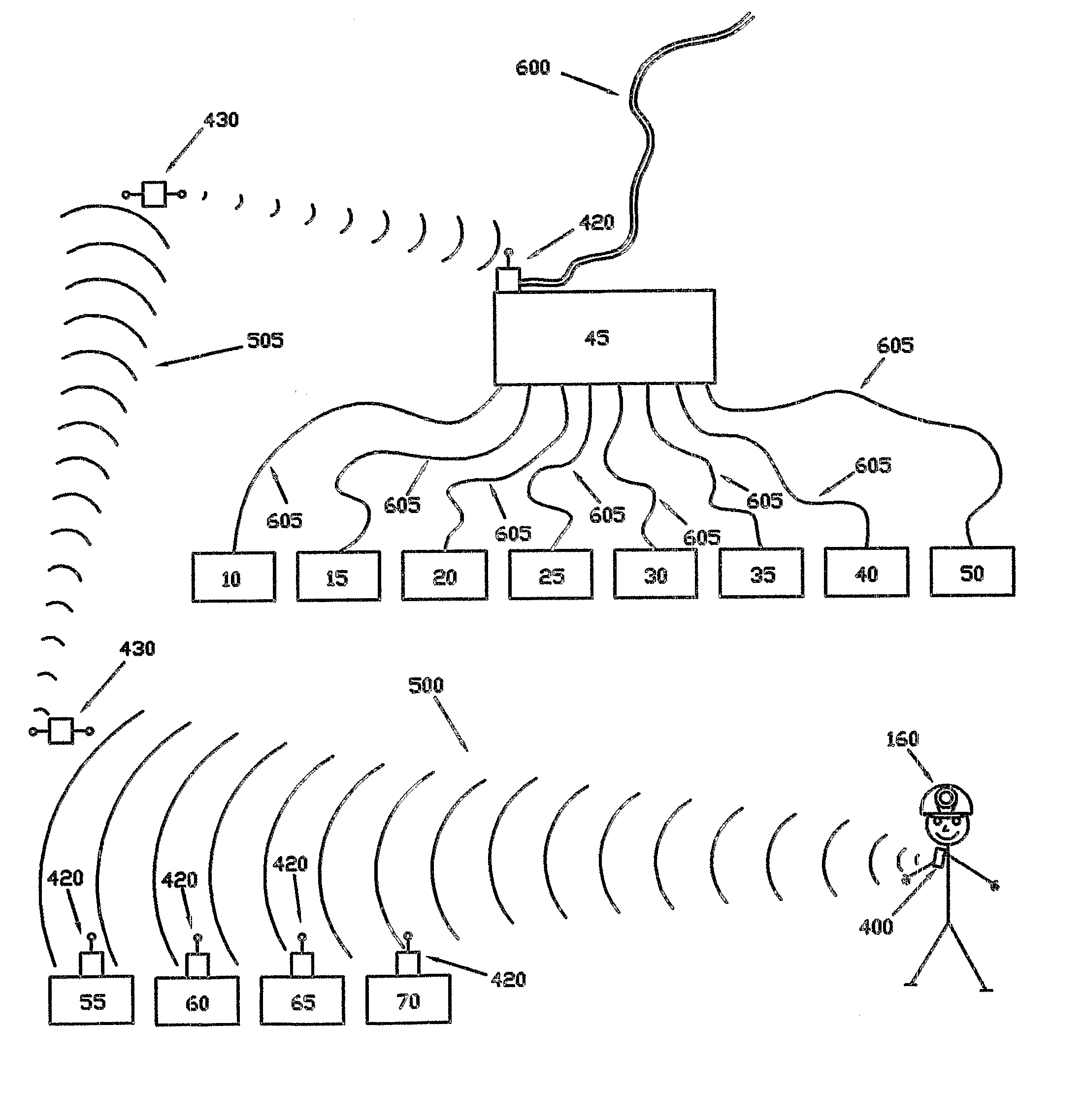
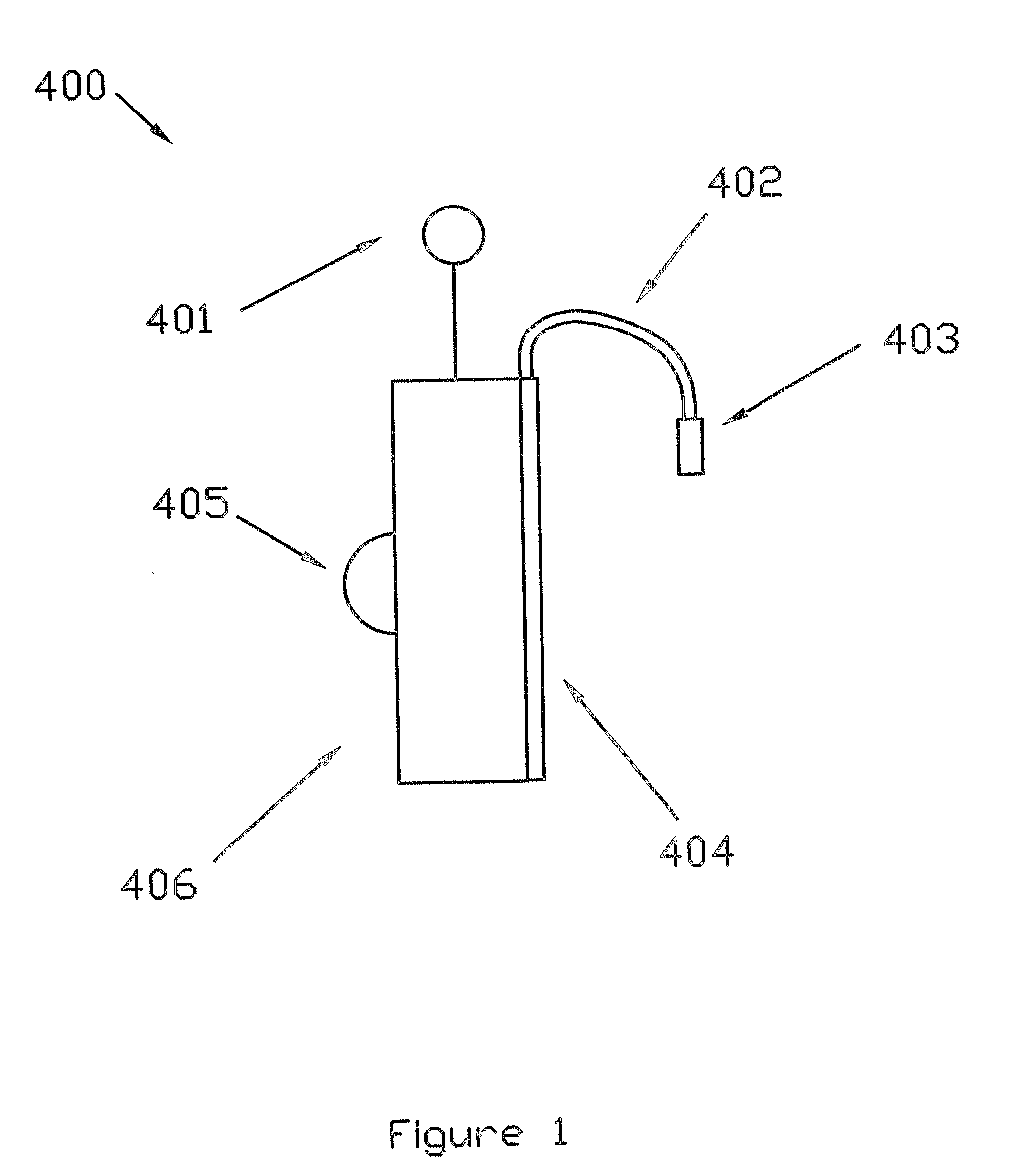
[0019] Turning first to FIG. 1, there is shown a personal wearable transmitter apparatus 400. The individual components of this device 400 may be based on prior technology. It is generally comprised of electrical components needed to generate and remotely transmit a specified radio signal when switch 405 is depressed. The enclosure 406 is designed to protect the internal components from all manner of environmental damage that may be found in mining, construction, manufacturing and other activities where humans are in close proximity to powered equipment. An anten...


PUM


Abstract

A method and arrangement for remotely stopping powered equipment in emergency situations. Embodiments of the invention include wearable radio remote transmitters (400) capable of transmitting a signal (500, 505) to powered equipment in the immediate area. A transmitter (400) desirably is located such that it can be quickly activated by the person wearing the transmitter, and may be equipped with a shock detection device capable of automatically activating the radio transmitter Powered equipment operating in the vicinity of transmitter-equipped personnel are fitted with receivers, electronics, actuator, batteries and/or electrical connections, as needed, to shutdown the equipment upon receiving a radio signal from a transmitter Sometimes receivers and amplifiers are located such that a transmitter's signal sent from any location in the area will reach all relevant equipment receivers with sufficient energy to activate the shutdown procedure. A preferred embodiment may include a manually activated transmitter (400) attached to a person's clothing and receivers and actuators mounted on all powered equipment within line-of-sight of this person.

Description

PRIORITY CLAIM [0001] This application claims the benefit of the filing date of U.S. Provisional Patent Application Ser. No. 60 / 575,448, filed May 28, 2004, for “Personal Radio Emergency Stop (PRES) Concept”.TECHNICAL FIELD [0002] This invention relates generally to safety devices and methods operable to stop equipment or machinery to protect personnel in the vicinity of such equipment and / or local environmental hazzards. BACKGROUND [0003] In many situations involving use of machinery or equipment, the operator of the potentially heavy powered machinery, or other equipment, is the only person with routine access to devices capable of quickly stopping the specific powered equipment this person is operating. In general, the operator is onboard the equipment using direct mechanical controls to operate the machine. Sometimes, the operator may be operating by radio remote control while in direct sight of the equipment or be using video and audio equipment for reference and remote control...

Claims


Application Information

Patent Timeline
Patent Type & Authority Applications(United States)
IPC IPC(8): G08C19/00E21F11/00G08C17/02
CPCG08C17/02E21F11/00
Inventor FREDERICK, JOHN R.
Owner FREDERICK JOHN R
Why Eureka
Try Eureka