Projection apparatus

a technology of projection apparatus and projection screen, which is applied in the field of projection screen, can solve problems such as difficulty in finding it, and achieve the effect of high flexibility in operation and easy maintenan

Inactive Publication Date: 2007-10-04
CORETRONIC
View PDF8 Cites 0 Cited by
  • Summary
  • Abstract
  • Description
  • Claims
  • Application Information

AI Technical Summary

Benefits of technology

[0010]In brief, the projection apparatus in the present invention permits a user to emit a wireless signal through a control panel to remotely control the projection module or transmit a control signal through a circuit to control the projection module after disposing the control panel into the concavity. Therefore, the projection apparatus has a high flexibility in operation. Moreover, the control panel and the projection apparatus are packed together by disposing the control panel into the concavity after use. Hence, the control panel is easier to keep and not so easy to lose.

Problems solved by technology

Since the infrared remote control 160 is a relatively small device, finding it is difficult.

Method used


Image

  • Projection apparatus
  • Projection apparatus
  • Projection apparatus

Examples


Embodiment Construction

[0020]Reference will now be made in detail to the present preferred embodiments of the invention, examples of which are illustrated in the accompanying drawings. Wherever possible, the same reference numbers are used in the drawings and the description to refer to the same or like parts.

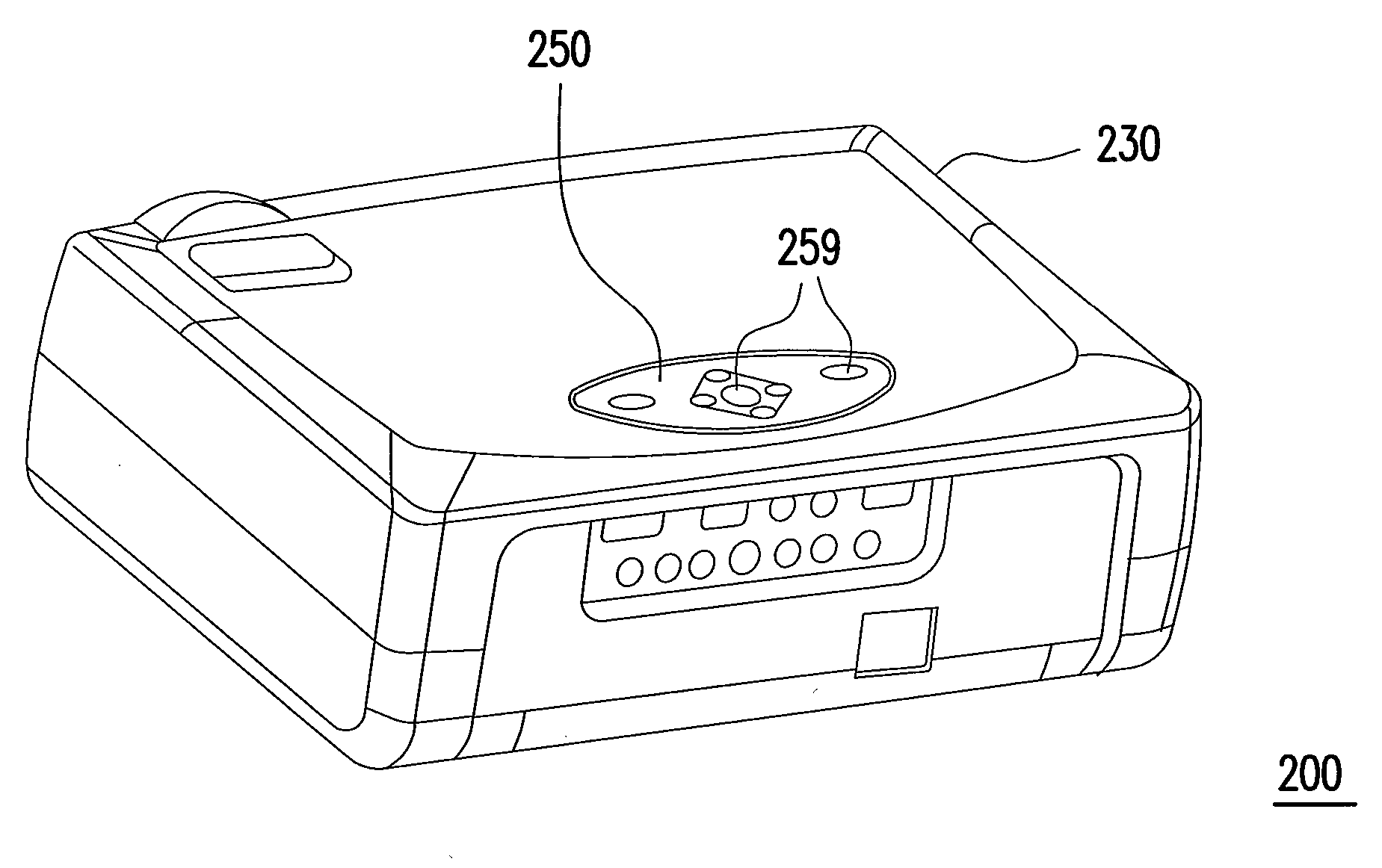
[0021]FIG. 2A is a perspective view of a projection apparatus according to one embodiment of the present invention. FIG. 2B is a block diagram showing the structure of the projection apparatus shown in FIG. 2A. FIG. 3A is a perspective view of the projection apparatus in FIG. 2A operated under remote control. FIG. 3B is a block diagram of the projection apparatus shown in FIG. 3A. As shown in FIGS. 2A, 2B, 3A and 3B, the projection apparatus 200 in the present invention includes a projection module 210, a control unit 220, a housing 230, a wireless-receiving unit 240 and a control panel 250. The projection module 210 is suitable for projecting an image on a screen. The control unit 220 is electricall...


PUM


Abstract

A projection apparatus including a projection module, a control unit, a housing, a wireless-receiving unit and a control panel is provided. The control unit is electrically connected to the projection module for controlling the projection module. The housing is suitable for accommodating the projection module and the control unit and has a concavity exposed outside. The wireless-receiving unit is disposed inside the housing and is electrically connected to the control unit. The control panel is detachably installed in the concavity. When the control panel is installed in the concavity, the control panel is electrically connected to the control unit such that the control panel is suitable for providing an electric signal to the control unit for controlling the projection module. When the control panel is detached from the concavity, the control panel is suitable for providing a wireless signal to the wireless-receiving unit for controlling the projection module.

Description

CROSS-REFERENCE TO RELATED APPLICATION[0001]This application claims the priority benefit of Taiwan application serial no. 95110855, filed Mar. 29, 2006. All disclosure of the Taiwan application is incorporated herein by reference.BACKGROUND OF THE INVENTION[0002]1. Field of the Invention[0003]The present invention relates to a display apparatus, and more particularly, to a projection apparatus.[0004]2. Description of Related Art[0005]FIG. 1A is a perspective view of a conventional projection apparatus. FIG. 1B is a block diagram showing the structure of the projection apparatus shown in FIG. 1A. As shown in FIGS. 1A and 1B, the conventional projection apparatus 100 includes a projection module 110, a control unit 120, a housing 130, a control panel 140, an infrared-receiving unit 150 and an infrared remote control 160. The projection module 110 projects an image on a screen. The control unit 120 is electrically connected to the projection module 110 for controlling the projection mo...

Claims


Application Information

Patent Timeline
Patent Type & Authority Applications(United States)
IPC IPC(8): G03B21/26
CPCG03B21/14G03B21/145
Inventor HSIEH, CHENG-FENGCHANG, FAN-CHIEHLIU, I-MING
Owner CORETRONIC
Why Eureka
Try Eureka