Denitration system and method which are capable of realizing direct utilization of agglomerate heat energy

A sintering and denitrification technology, applied in the field of denitrification system, can solve the problems of affecting the solid balance of the wet desulfurization system and the crystallization of by-products, destroying the long-term stable operation of the system, and low denitrification efficiency, so as to achieve high utilization efficiency, large operating flexibility, The effect of reducing system investment

Pending Publication Date: 2017-07-28
MCC CAPITAL ENGINEERING & RESEARCH
View PDF15 Cites 10 Cited by
  • Summary
  • Abstract
  • Description
  • Claims
  • Application Information

AI Technical Summary

Problems solved by technology

In this case, due to the limited catalytic effect of sinter and the serious accumulation of ammonium sulfate at the rear end of waste heat recovery due to the escape of ammonia, it is necessary to control the amount of ammonia injection, which can only achieve a low denitrification efficiency; based on the practice of domestic sinter waste heat recovery, through The flue gas after sintering will carry a large amount of dust, which still exists after waste heat recovery. In this case, this flue gas is directly sent to ammonia desulfuriz

Method used


Image

  • Denitration system and method which are capable of realizing direct utilization of agglomerate heat energy
  • Denitration system and method which are capable of realizing direct utilization of agglomerate heat energy

Examples


Embodiment 1

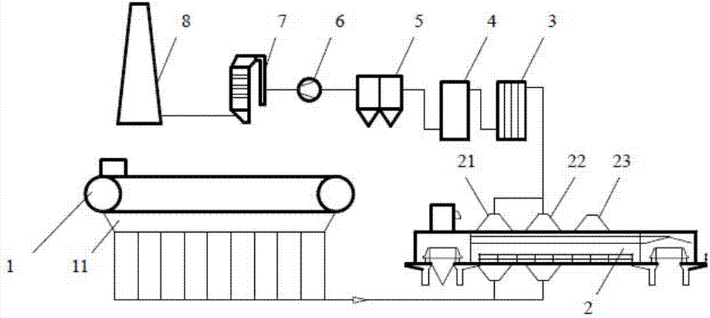
[0048] See figure 1 , which is a diagram of the low-temperature denitrification system that directly utilizes the heat of sinter in this embodiment. The low-temperature denitrification system includes a sintering machine 1, a sinter cooling device 2, a waste heat recovery device 3, a dry desulfurization device 4, a dust removal device 5, and a denitrification reactor 7 and chimney 8; the sintering machine is provided with a sintering machine bellows 11, and the sinter cooling equipment 2 is an existing ring cooler, which is provided with a first cooling equipment wind box 21 (high temperature section wind box), a cooling equipment second section bellows 22 (medium temperature section bellows) and the third section bellows 23 (low temperature section bellows) of cooling equipment, the flue gas outlet of the sintering machine bellows 11 is connected to the first section bellows 21 of the cooling equipment and the The flue gas inlet of the second-stage air box 22 of the cooling e...

Embodiment 2

[0057] The low-temperature denitrification system used in this embodiment is basically the same as that in Embodiment 1, except that this embodiment is an existing sintering machine, which itself has a sintering machine dust removal device (not shown in the figure), and the dust removal device is an electric dust collector. device, the electrostatic precipitator is installed on the connecting pipeline between the wind box 11 of the sintering machine, the wind box 21 of the first section of the cooling equipment, and the wind box of the second section of the cooling equipment.

[0058] The flue gas drawn from the wind box 11 of the existing sintering machine is collected together. At this time, the SO in the flue gas 2 The concentration is 2000mg / Nm 3 , NO x The concentration is 500mg / Nm 3 , the dust content is 2000mg / Nm 3 , the flue gas temperature is 140°C, the sintering flue gas is passed through the electrostatic precipitator to reduce the dust content to 150mg / Nm 3, an...

Embodiment 3

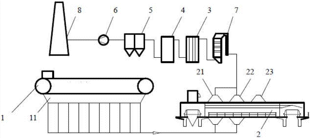
[0060] See figure 2 , which is a diagram of the medium-temperature denitrification system that directly utilizes the heat of sinter in this embodiment. The medium-temperature denitrification system includes a sintering machine 1, a sinter cooling device 2, a waste heat recovery device 3, a dry desulfurization device 4, a dust removal device 5, and a medium-temperature denitrification reaction 7 and chimney 8; the sintering machine is provided with a sintering machine air box 11, and the sinter cooling equipment 2 is an existing ring cooler, which is provided with a cooling equipment first section air box 21 (high temperature section air box), a cooling equipment first The second section wind box 22 (medium temperature section wind box) and the third section wind box 23 (low temperature section wind box) of the cooling equipment, the flue gas outlet of the sintering machine bellows 11 is connected to the first section wind box 21 and The flue gas inlet of the second-stage wind...


PUM


Abstract

The invention provides a denitration system and a method which are capable of realizing direct utilization of agglomerate heat energy. The denitration system comprises a sintering machine, a cooling equipment, a waste heat recycling device, a dry desulfurization device, a dust collector, a blower fan, a denitration reactor, and a chimney; an exhaust gas outlet of an air bellow of the sintering machine is connected with an exhaust gas outlet of a first segment air bellow and an exhaust gas outlet of a second segment air bellow; the exhaust gas outlet of the first segment air bellow and the exhaust gas outlet of the second segment air bellow are connected with the waste heat recycling device, and then the waste heat recycling device is connected with the dry desulfurization device, the dust collector, the blower fan, and the chimney via pipelines in series connection successively; when the denitration reactor is a low-temperature denitration reactor, the denitration reactor is arranged between the blower fan and the chimney; and when the denitration reactor is a middle-temperature denitration reactor, the denitration reactor is arranged among the exhaust gas outlet of the first segment air bellow, the exhaust gas outlet of the second segment air bellow, and the waste heat recycling device. The denitration system and the method are capable of realizing direct utilization of agglomerate heat energy, low temperature denitration reaction of sintering exhaust gas is realized without consumption of extra energy, high efficiency conversion of NOx is realized, denitration rate is as high as 80 to 90%, agglomerate embrittlement is not caused, and agglomerate waste heat is recycled.

Description

technical field [0001] The invention relates to a denitrification system and method, in particular to a denitrification system and method which directly utilize the heat of sintered ore. Background technique [0002] With the development of the national economy and the improvement of people's living standards, people pay more and more attention to environmental issues. As a pollutant closely related to air quality, nitrogen oxides (NO x ) has been receiving national attention. According to the statistics of the Ministry of Environmental Protection, in 2014, the national industrial waste gas emissions of NO x A total of 14.048 million tons, while the NO emissions from ferrous metal smelting and rolling processing x It is one of the three major emission sources. [0003] The flue gas emitted by sintering machines in iron and steel enterprises (ferrous metal smelting) is the key NO x emission sources, and its denitrification has received more and more attention. The "Twelf...

Claims


Application Information

Patent Timeline
IPC IPC(8): B01D53/83B01D53/50B01D46/02B01D53/90B01D53/56F27D17/00
CPCB01D46/02B01D53/508B01D53/8631B01D53/90F27D17/004F27D17/008Y02P10/25
Inventor 周向朱繁崔岩王介超张传波
Owner MCC CAPITAL ENGINEERING & RESEARCH
Why Eureka
Try Eureka