
Method of processing, for example of inserting contours of a digital image and corresponding device

Inactive Publication Date: 2007-10-04
STMICROELECTRONICS SRL +1
View PDF9 Cites 2 Cited by
  • Summary
  • Abstract
  • Description
  • Claims
  • Application Information

AI Technical Summary

Benefits of technology

[0014] According to an embodiment, the main value corresponds to the amplitude of the contour, that is to say to the deviation between the maximum amplitude of a pixel and the minimum amplitude of another pixel. This embodiment has the advantage of limiting the number of operations to be performed. The main cue may be normalized, and may correspond to the contour amplitude divided by this same amplitude. The main cue therefore has a unit value. The method may comprise a step of post-filtering of the contour zones of the magnified image, according to a post-filtering software tool, chosen as a function of the dimensions of each contour zone.

Problems solved by technology

However, if the contour processing used can reduce certain artifacts appearing during the transformation of the image, for example, the appearance of halos at the level of the contours of the image, it may aggravate other phenomena, such as the appearance of oscillations (“ringing”) which may be particularly detrimental for certain applications.

Method used


Image

  • Method of processing, for example of inserting contours of a digital image and corresponding device
  • Method of processing, for example of inserting contours of a digital image and corresponding device
  • Method of processing, for example of inserting contours of a digital image and corresponding device

Examples


Embodiment Construction

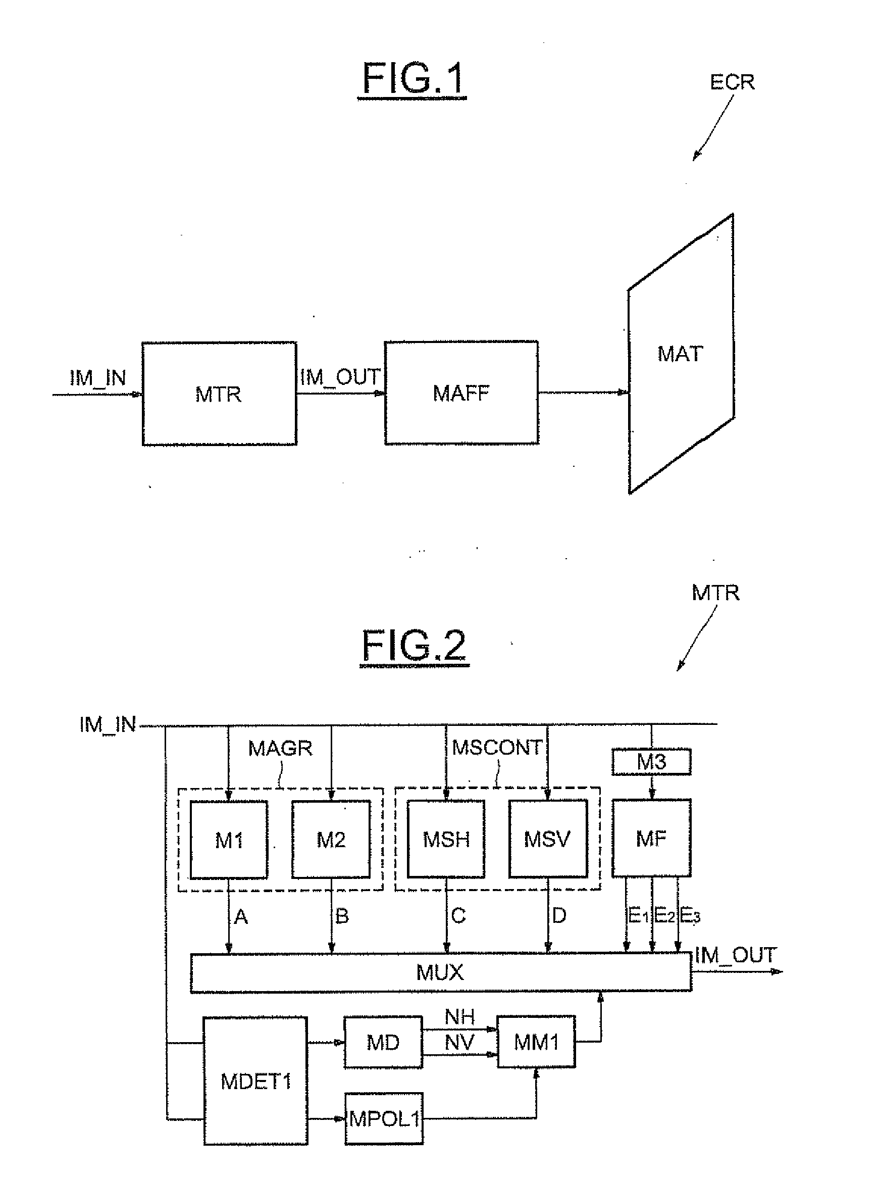
[0033] We refer to FIG. 1 where the reference ECR represents a screen, for example a plasma screen. This screen ECR comprises means of processing MTR of a sampled digital input image IM-TN, and delivers as output a processed digital image IM-OUT. This processed image IM-OUT is delivered to display means or a display MAFF able to adapt the image so as to display it on the display matrix MAT of the screen ECR.

[0034] We refer now to FIG. 2, which illustrates an embodiment of the processing means or a processor MTR. The processing means MTR comprise in this example, magnifying means or a magnifier MAGR able to perform a magnification of the digital input image IM-IN. However, it is possible to perform any other conventional processing of the image such as an increasing of its resolution, or else the application of a filter of poly-phase type. The magnifying means MAGR receive as input the input image IM-IN and deliver as output a magnified input image.

[0035] In this example, the input...


PUM


Abstract

A device processes an initial digital image with at least one contour zone. The device may have a magnifier able to magnify the initial image into a magnified digital image. The magnifier may have a detector able to detect the contour zones of the initial digital image, a determinater able to determine the size, in terms of number of pixels, of each contour zone, and a second magnifier able to magnify each contour zone using of a software tool, chosen as a function of the size of each contour zone, from among a set of magnifying software tools.

Description

FIELD OF THE INVENTION [0001] The invention relates to the processing of digital images, in particular the processing of the contour zones of a digital image that has undergone a transformation, for example a magnification. BACKGROUND OF THE INVENTION [0002] Conventionally, the image minus contour is processed as a whole, and in parallel a processing of the horizontal and vertical contours is performed for a two-dimensional image. On completion of each processing, identical for all the contours, the latter are inserted into the image according to a conventional linear procedure. [0003] Generally the latter employs a mixer between the vertical and horizontal processed contours obtained, according to the orientation of this contour in the image, and the resulting contour is inserted directly at its position in the image. This procedure is for example described in the article: Xin Li, Michael T. Orchard: New edge directed interpolation; IEEE Trans, On Image Processing, Vol. 10, No. 10,...

Claims


Application Information

Patent Timeline
IPC IPC(8): G06K9/34
CPCG06T3/403
Inventor LEBOWSKY, FRITZHUANG, YONGWANG, HAIYUN
Owner STMICROELECTRONICS SRL
Learn More