Bar for a braked aircraft wheel

a technology for aircraft wheels and bars, which is applied in the direction of braking discs, aircraft braking arrangements, manufacturing tools, etc., can solve the problems of slow wheel rotation speed and controlled pressure applied

Pending Publication Date: 2022-07-28
SAFRAN LANDING SYSTEMS
View PDF0 Cites 0 Cited by
  • Summary
  • Abstract
  • Description
  • Claims
  • Application Information

AI Technical Summary

Problems solved by technology

Controlled pressure applied to the stack of disks gives rise to friction between the facing disks, and thus to a braking torque that slows down the rotation of the wheel.

Method used


Image

  • Bar for a braked aircraft wheel
  • Bar for a braked aircraft wheel
  • Bar for a braked aircraft wheel

Examples


Embodiment Construction

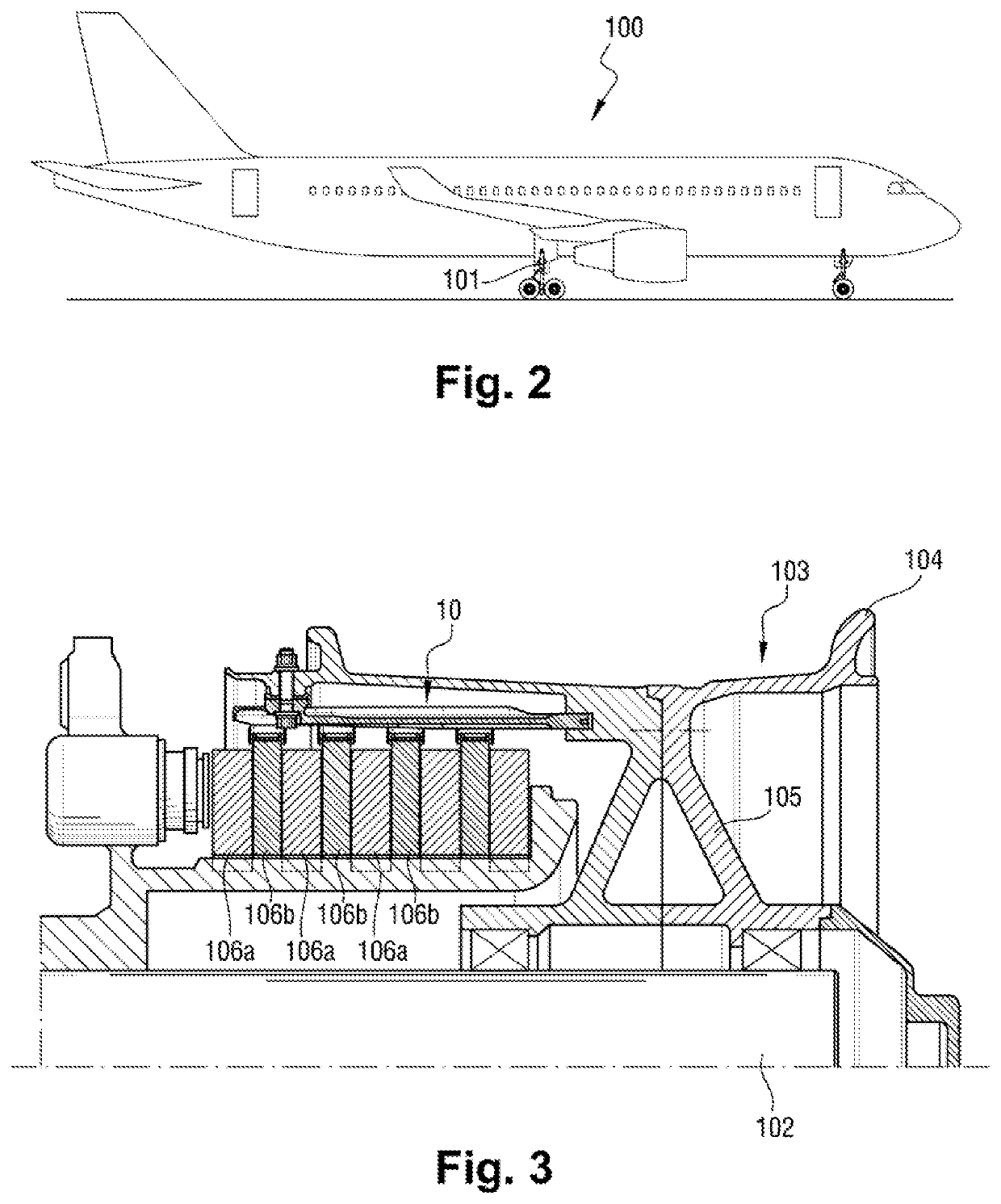
[0033]With reference to FIGS. 2 and 3, an aircraft 100 of the invention comprises a structure provided with undercarriages 101. Each undercarriage 101 comprises a leg having one end hinged to the structure of the aircraft 100 and an opposite end carrying an axle 102 on which a wheel 103 is rotatably mounted.

[0034]The wheel 103 comprises a rim 104 and a web 105 connecting the rim 104 to a hub that is rotatably received on the axle 102 so that an inside surface of the rim 104 extends facing an outside surface of the hub and co-operates with the hub to define a space for receiving a stack of brake disks. The stack comprises stator disks 106a prevented from rotating relative to the leg of the undercarriage and rotor disks 106b including peripheral notches that receive bars, given overall reference 10, which bars are fastened to the inside surface of the rim 104.

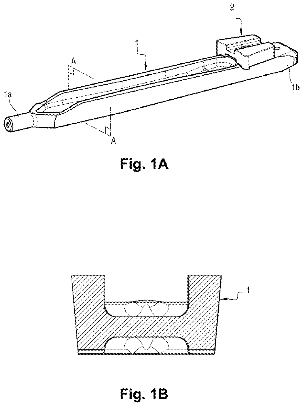
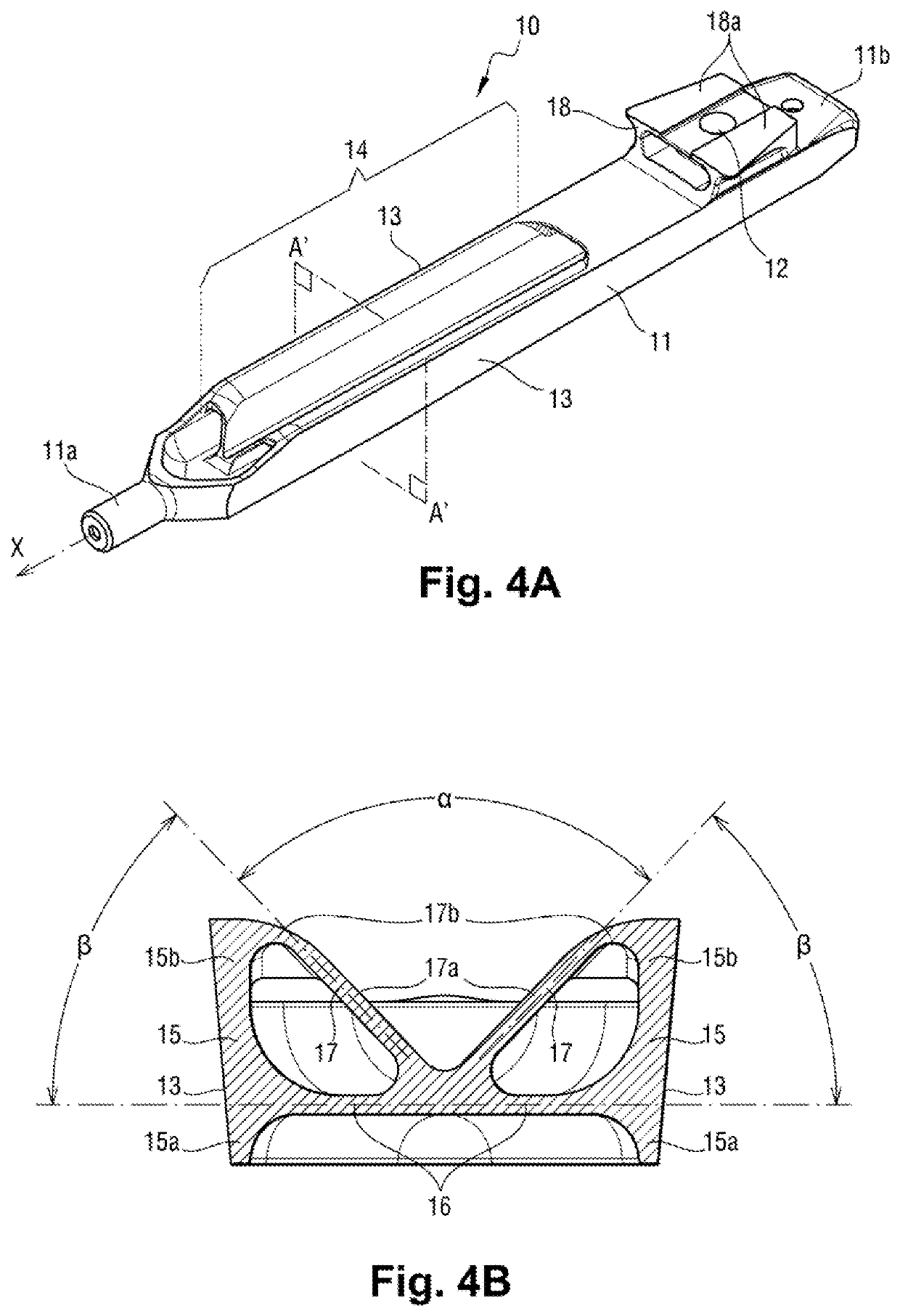
[0035]With reference to FIG. 4A, each bar 10 comprises a body 11 extending along a longitudinal axis X. The body 11 has a first...


PUM

PropertyMeasurementUnit
weightaaaaaaaaaa
angleaaaaaaaaaa
thicknessaaaaaaaaaa

Abstract

The invention relates to a bar (10) for a braked aircraft wheel (103), the bar being for fitting to a rim (104) of the wheel in order to drive rotor brake disks (106b) in rotation. The bar comprises a substantially rectilinear body (11) having at least one segment (14) including two wings (15) connected together by a core (16) and intended to co-operate with the rotor disks. At least one brace element (17) connects a free edge of each of the wings to a central portion of the core.

Description

[0001]The present invention relates to the field of aviation and, more particularly, to braking aircraft wheels.BACKGROUND OF THE INVENTION[0002]Aircraft wheels are known that are mounted on undercarriages and that are provided with respective brakes. Such a brake generally comprises stator disks arranged in alternation with rotor disks that are driven in rotation by Inconel® alloy bars secured to the inner periphery of a rim of the wheel. The bars are received in peripheral notches in the rotor disks, and they extend in a direction that is substantially parallel to the axis of rotation of said wheel. Controlled pressure applied to the stack of disks gives rise to friction between the facing disks, and thus to a braking torque that slows down the rotation of the wheel.[0003]The bars may be made integrally with the rim of the wheel, or they may be fitted thereto. With reference to FIG. 1A, certain prior art bars 1 have a cylindrical tail at one end 1a for engaging in orifices made in...

Claims


Application Information

Patent Timeline
Patent Type & Authority Applications(United States)
IPC IPC(8): F16D65/12F16D55/36B64C25/44B33Y80/00
CPCF16D65/12F16D55/36F16D2065/1364B33Y80/00F16D2250/00B64C25/44B64C25/42B60B25/00B33Y70/00F16D2065/1372F16D2200/0026B33Y10/00B23K26/342F16D2065/138F16D2065/1392
Inventor SOULA, AURÉLIEPALAZZOLI, PATRICEDAULNY, ALEXANDRECARATY, ARNAUD
Owner SAFRAN LANDING SYSTEMS
Why Eureka
Try Eureka