Probe for inspecting the surface of a circumferential slot in a turbojet disk by means of eddy currents

a turbojet disk and circumferential slot technology, applied in the direction of magnetic property measurement, material magnetic variables, instruments, etc., can solve the problems of reducing accuracy, falsifying measurement, and requiring very regular inspection of slots of this type, so as to reduce the influence of human factors, reduce the number of inspection operations, and limit the risk of error

Active Publication Date: 2014-10-21
SN DETUDE & DE CONSTR DE MOTEURS DAVIATION S N E C M A
View PDF12 Cites 1 Cited by
  • Summary
  • Abstract
  • Description
  • Claims
  • Application Information

AI Technical Summary

Benefits of technology

[0023]By means of the provisions of the present invention, it is possible to acquire all of the data in a single scanning revolution of the probe. The two side faces of the slot are inspected simultaneously by the two multi-element sensors. Furthermore, good contact may be maintained between the multi-element sensors and the disk by means of one or more return springs arranged between the two sensors that are placed back to back. By reducing the number of inspection operations, the probe of the invention reduces the influence of the human factor on the measurement results, thereby limiting risks of error. By providing good contact between the probe and the side faces of the slot, the invention also enables the measurement results to be refined. Finally, in spite of the poor access to the shape that is to be inspected, and because of the automatic self-balancing between the sensors placed back to back, it is possible to avoid phenomena of the stem flexing, which can lead to contact being lost between the sensors and the surfaces for inspection.

Problems solved by technology

As a result, slots of this type require very regular inspection.
Given the poor accessibility of the side faces, it is common practice to verify their surface state by performing inspection by means of eddy currents.
The large number of measurements and calculations, and also the difficulty in positioning the sensor against the surface for examination, decrease the accuracy of the results.
Furthermore, insofar as the known system allows only one side of the slot to be inspected, problems associated with the stem flexing appear over time, thereby falsifying the measurement results because of the multi-element sensor being poorly oriented relative to the surface for inspection.

Method used


Image

  • Probe for inspecting the surface of a circumferential slot in a turbojet disk by means of eddy currents
  • Probe for inspecting the surface of a circumferential slot in a turbojet disk by means of eddy currents
  • Probe for inspecting the surface of a circumferential slot in a turbojet disk by means of eddy currents

Examples


Embodiment Construction

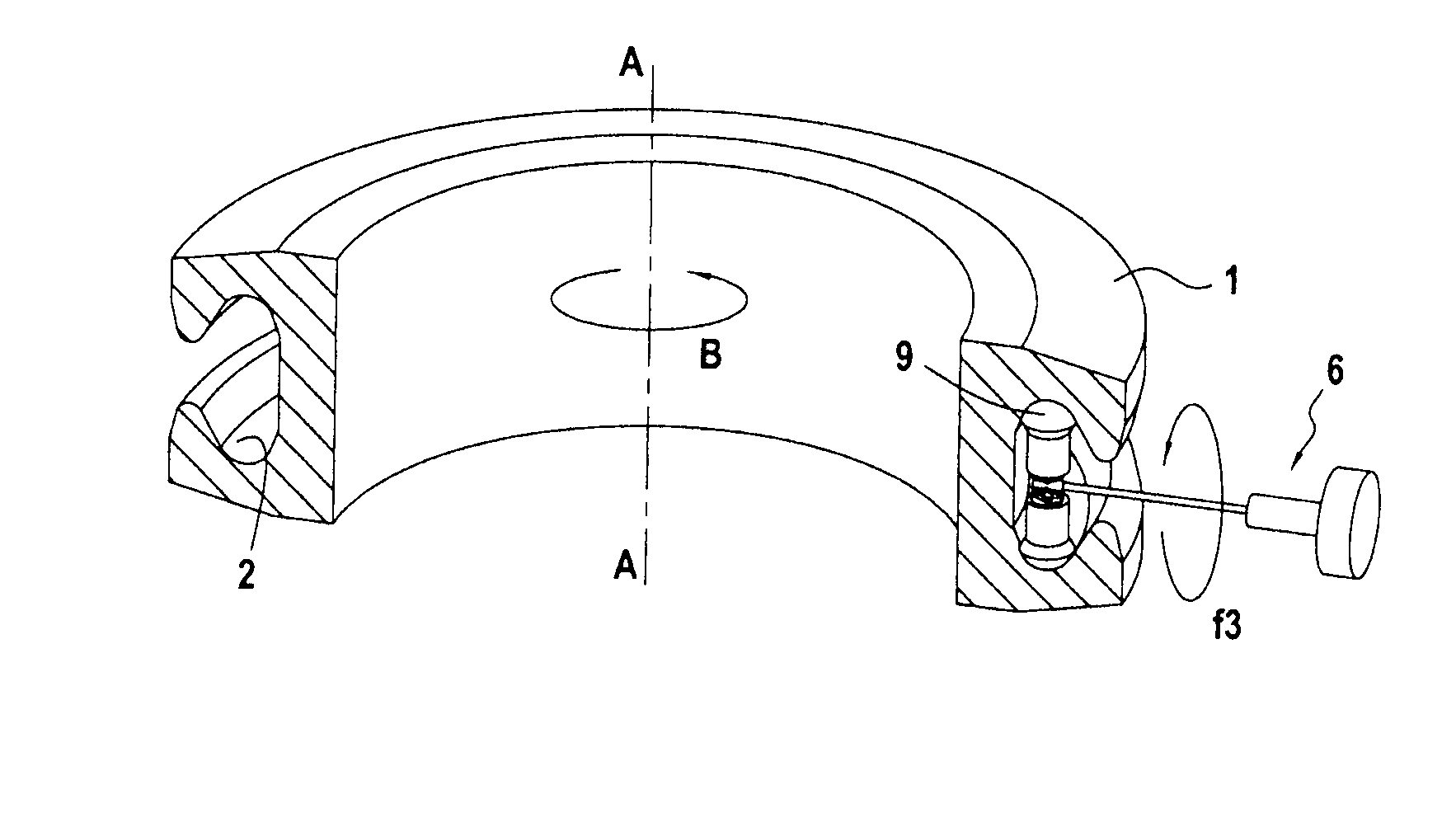
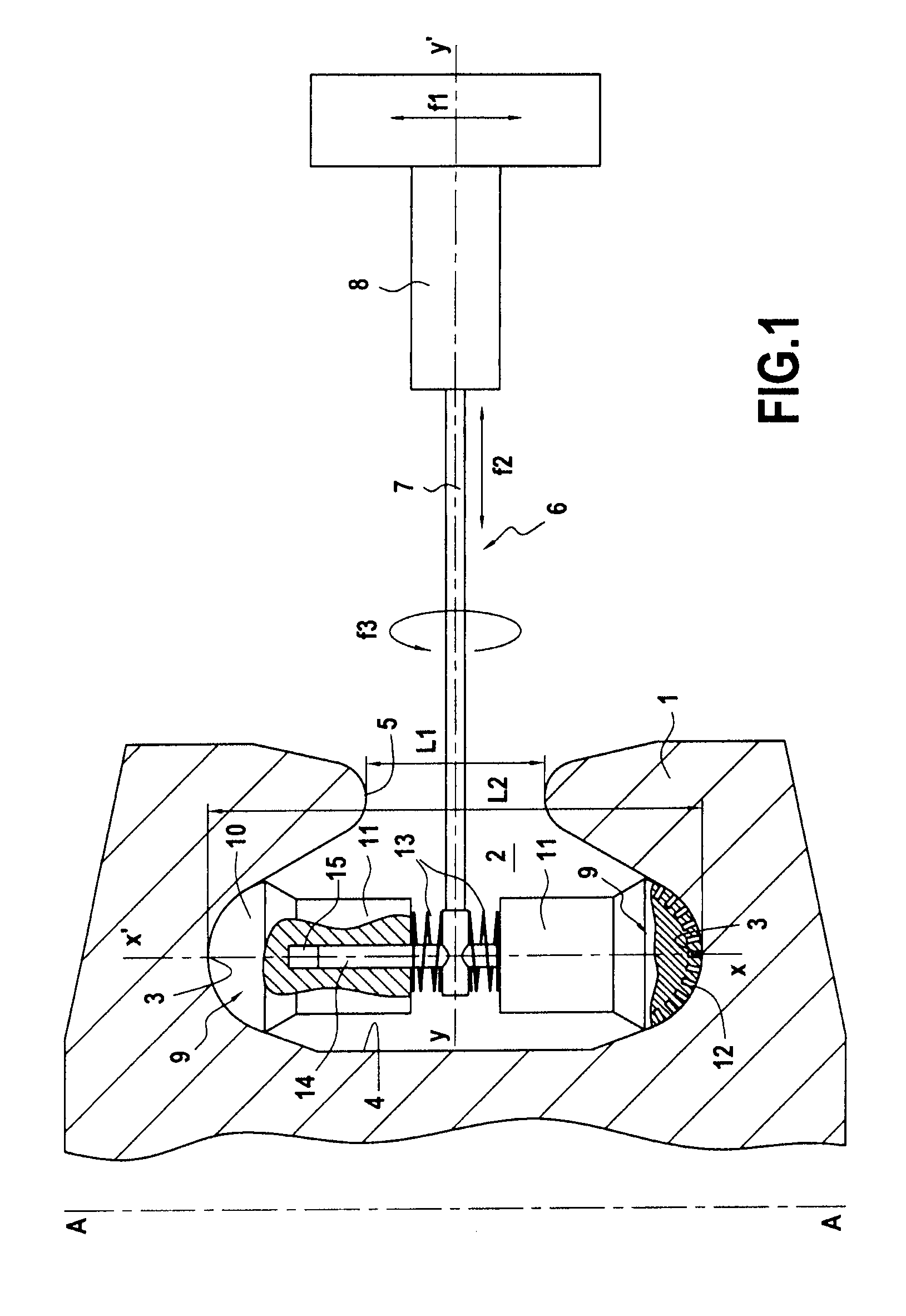
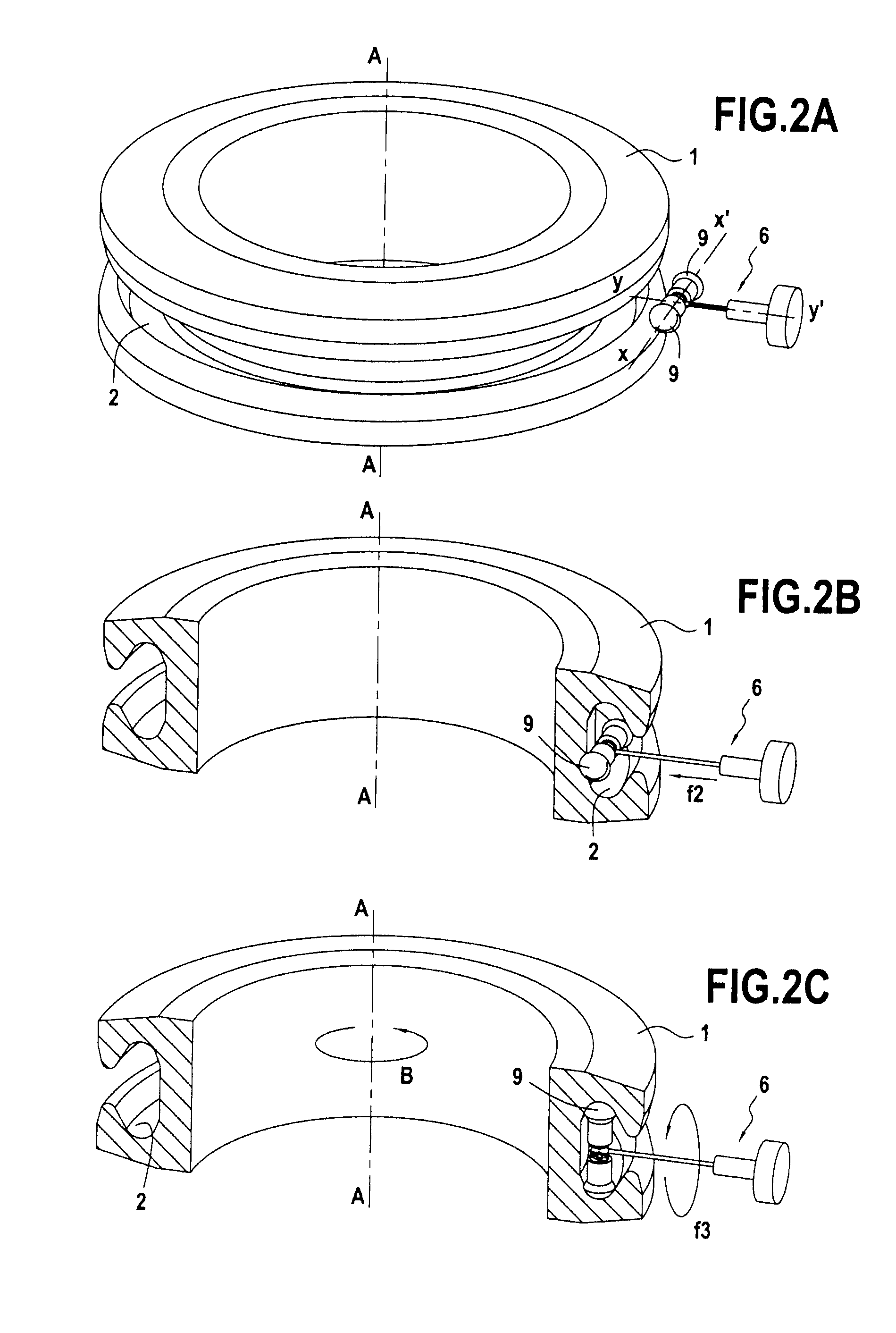
[0027]FIG. 1 shows a portion of a turbojet disk 1 having a circumferential slot 2 machined therein for receiving a series of blades. The slot has a substantially cylindrical central face 4 about an axis A-A, and two side faces 3 of concave annular shape. The slot 2 opens out via an annular opening 5 of width L1 measured in the axial direction. The width L1 of the opening 5 is less than the greatest width L2 of the slot 2 measured in the axial direction, i.e. between its side faces 3.

[0028]A probe of the present invention is described with reference to FIG. 1. The probe 6 is constituted by a stem 7, a support 8, and two multi-element sensors 9. Arrows fl, f2, and f3 represent the degrees of freedom of the stem 7, determined by ball slideways and springs that are not shown. These degrees of freedom are defined below with reference of the frame of reference of the turbojet disk. In particular, arrow fl corresponds to the stem being moved along the axis of the disk, arrow f2 corresponds...


PUM

PropertyMeasurementUnit
angleaaaaaaaaaa
angleaaaaaaaaaa
degrees of freedomaaaaaaaaaa

Abstract

A probe for eddy current monitoring of the surface of a circumferential slot formed in a turbojet disk. The probe includes a stem fastened to a support and a first multi-element sensor constrained to move with the stem and configured to be inserted into the circumferential slot to perform the inspection, and a second multi-element sensor. The two multi-element sensors are disposed back to back, and the stem of the probe is mounted to pivot about its own axis to enable the two multi-element sensors to be inserted in the slot.

Description

BACKGROUND OF THE INVENTION[0001]1. Field of the Invention[0002]The present invention relates to a probe for inspecting surface anomalies and irregularities of a circumferential slot in a turbojet disk by means of eddy currents.[0003]2. Description of the Related Art[0004]The circumferential slot of a turbojet disk is intended to receive a series of blades and it is subjected to high levels of stress when the turbojet is in operation, in particular on its faces of concave angular shape (referred to below as the “side faces” of the slot). As a result, slots of this type require very regular inspection. Given the poor accessibility of the side faces, it is common practice to verify their surface state by performing inspection by means of eddy currents. This type of inspection consists in scanning the surface for examination by means of a probe fitted with a sensor that, by creating an electromagnetic field, produces eddy currents in the part under inspection. In practice, it is usuall...

Claims


Application Information

Patent Timeline
Patent Type & Authority Patents(United States)
IPC IPC(8): G01N27/90G01N27/82
CPCG01N27/904G01N27/9033G01N27/9006
Inventor CABANIS, PATRICKCHEYNET, SANDRAGAISNON, PATRICKRAVIZE, LUC
Owner SN DETUDE & DE CONSTR DE MOTEURS DAVIATION S N E C M A
Why Eureka
Try Eureka