

Plug-in unit
a plug-in unit and plug-in technology, applied in the field of plug-in units, can solve the problems of troublesome storage of fiber optic cables and difficulty in increasing the number of fiber optic cables connectable to the plug-in unit, and achieve the effect of easy-to-use the effect of increasing the number of connectable fiber optic cables
- Summary
- Abstract
- Description
- Claims
- Application Information
AI Technical Summary
Benefits of technology
Problems solved by technology
Method used
Image

Examples
first embodiment
1. First Embodiment
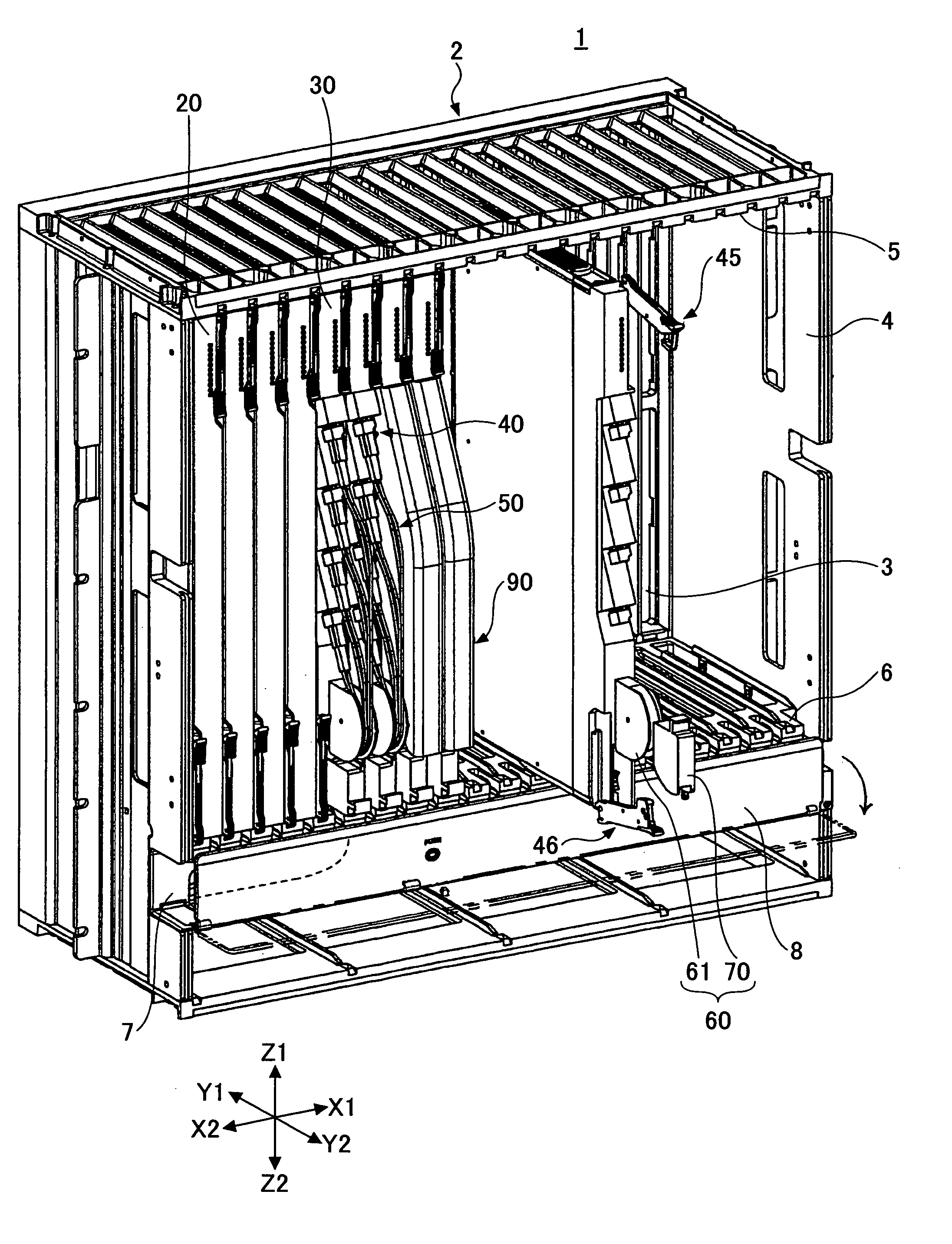
[0032]FIG. 1 is a perspective view of an electronic apparatus 1 according to the first embodiment of the present invention. Arrows X1-X2 show the width directions, Y1-Y2 show the depth directions, and Z1-Z2 show the height direction. The Y2 side is the front of the electronic apparatus 1.
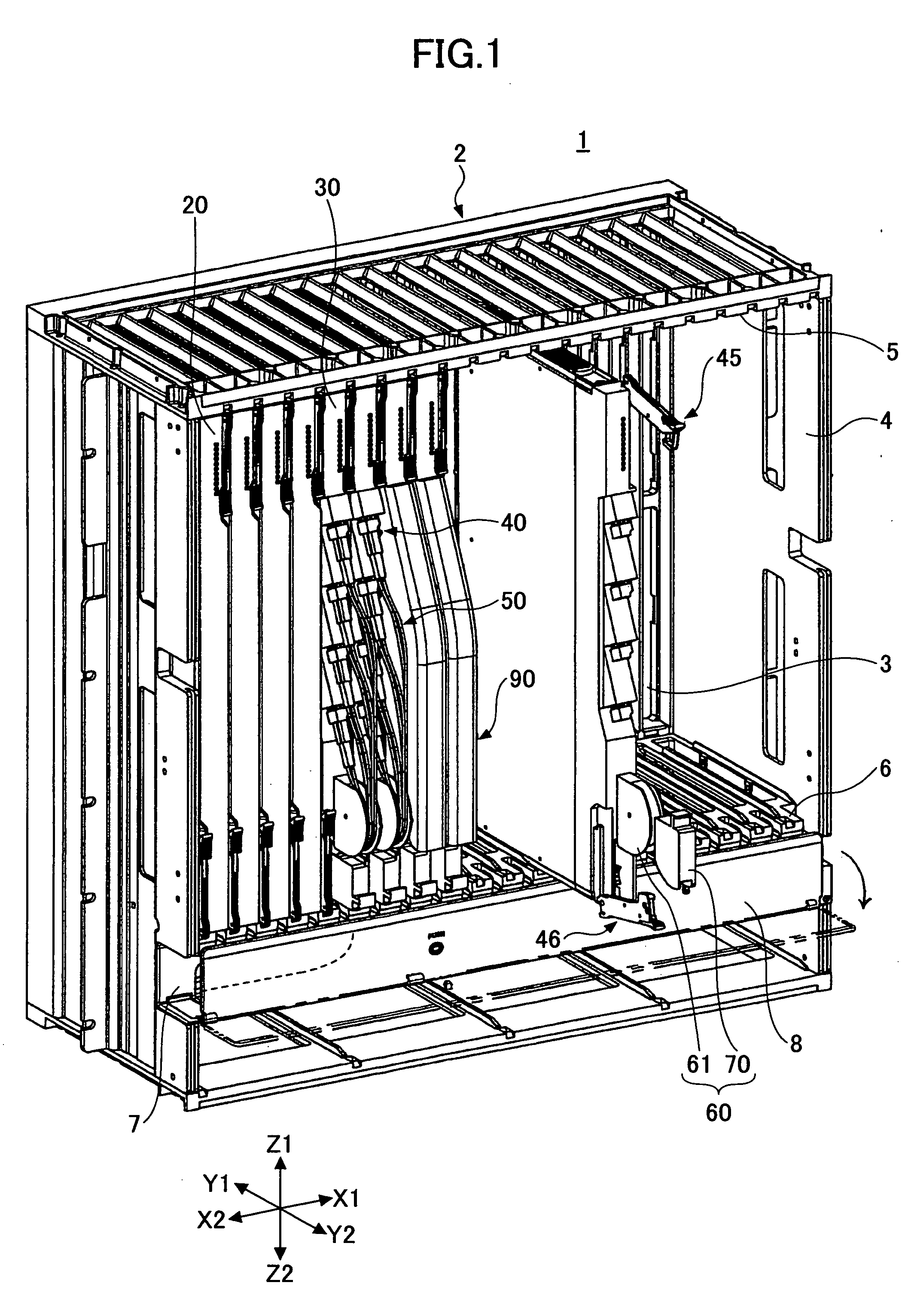
[0033]The electronic apparatus 1 includes a subrack 2. In the subrack 2, plug-in units 20 having no optical interface and optical plug-in units 30 each having optical interfaces on its front face are installed side by side. Plug-in units are inserted into the subrack 2 from the Y2 side.
[0034]In FIG. 1, four optical plug-in units 30 are installed. Fiber optic cables are connected to two of the optical plug-in units 30 and are guided along corresponding paths. The other two optical plug-in units 30 are covered by protective covers. Also, in FIG. 1, another optical plug-in unit 30, to which no fiber optic cable is connected, is being inserted into the subrack 2.
[0035]The subrack 2 is...
second embodiment
2. Second Embodiment
[0072]FIG. 14 is a perspective view of an optical plug-in unit 30A according to the second embodiment of the present invention. The optical plug-in unit 30A includes an extra fiber optic cable length handling mechanism 60A in place of the extra fiber optic cable length handling mechanism 60 of the optical plug-in unit 30. The extra fiber optic cable length handling mechanism 60A includes a second guiding member 70A in place of the second guiding member 70 of the extra fiber optic cable length handling mechanism 60.
[0073]FIG. 15 is an enlarged view of the second guiding member 70A. The second guiding member 70A includes a roller 100 with radius R1.
[0074]As shown in FIGS. 16A through 17B, the extra fiber optic cable length handling mechanism 60A is operated by rotating the second guiding member 70A. When the second guiding member 70A is rotated as shown in FIGS. 16A, 17A, and 17B, the roller 100 pushes the fiber optic cables 50 and in turn the roller 100 is rotated...
third embodiment
3. Third Embodiment
[0075]FIG. 18 is a perspective view of an optical plug-in unit 30B according to the third embodiment of the present invention. The optical plug-in unit 30B includes an extra fiber optic cable length handling mechanism 60B in place of the extra fiber optic cable length handling mechanism 60 of the optical plug-in unit 30. The extra fiber optic cable length handling mechanism 60B includes a first guiding member 61B in place of the first guiding member 61 of the extra fiber optic cable length handling mechanism 60.
[0076]FIG. 19 is an enlarged view of the first guiding member 61B. The first guiding member 61B is formed by bending a steel wire 110 and includes a fiber optic cable guiding part 111 for guiding the fiber optic cables 50. The fiber optic cables 50 are guided through the fiber optic cable guiding part 111.
[0077]When an operator's finger touches the first guiding member 61B, it bends flexibly; when the operator's finger moves away, it returns to its original...
PUM
 Abstract
Description
Claims
Application Information