Enhanced serpentine cooling with U-shaped divider rib

Active Publication Date: 2007-10-04
RAYTHEON TECH CORP
View PDF3 Cites 11 Cited by
  • Summary
  • Abstract
  • Description
  • Claims
  • Application Information

AI Technical Summary

Benefits of technology

[0006] In accordance with the present invention, a cooling passageway is provi

Problems solved by technology

Heat transfer tests have shown that this configuration can be inadequate and cooling losses may be encountered due to poorly developed flow st

Method used


Image

  • Enhanced serpentine cooling with U-shaped divider rib
  • Enhanced serpentine cooling with U-shaped divider rib
  • Enhanced serpentine cooling with U-shaped divider rib

Examples


Embodiment Construction

)

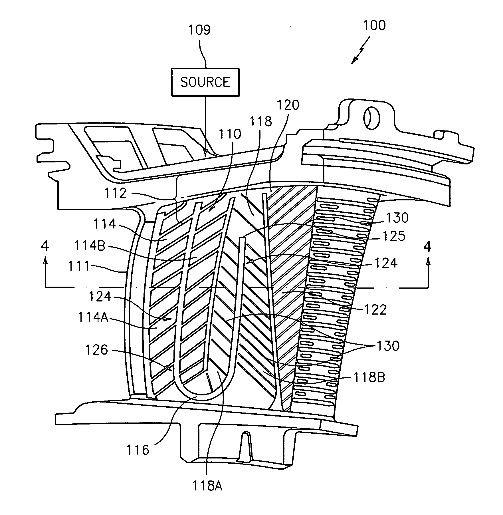
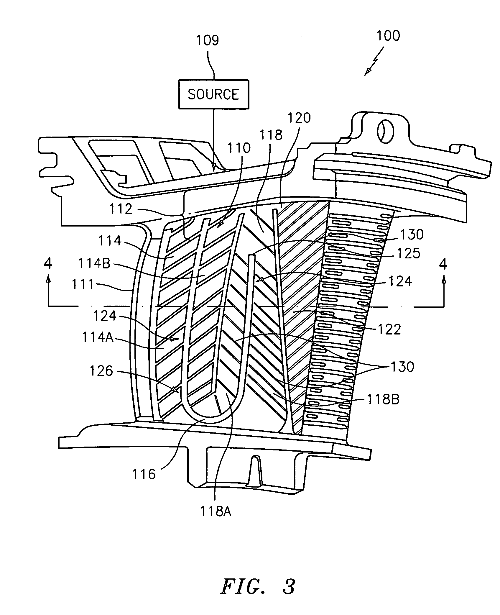
[0016] Referring now to FIGS. 3 and 4 of the drawings, there is shown an airfoil portion 111 of a turbine engine component 100 having an enhanced serpentine cooling passageway 110. The passageway 110 has a serpentine configuration with a fluid inlet 112, an inlet channel 114, a first turn 116, an intermediate channel 118, a second turn 120, and an outlet channel 122. The fluid inlet 112 may communicate with a source 109 of cooling fluid. The passageway 110 further has a U-shaped divider rib 124 which may extend from the inlet 112 to divide the channel 114 into a first channel 114A and a second channel 114B.

[0017] The U-shaped divider rib 124 allows a split of the cooling fluid entering the passageway 110 into two flow streams to be more easily controlled and to be more uniformly distributed. The U-shaped or arcuately shaped portion 126 of the divider rib 124 assists in guiding the cooling fluid around the first turn 116 in each of the channels 114A and 114B.

[0018] As can be seen ...


PUM


Abstract

A cooling passageway for use in an airfoil portion of a turbine engine component having a pressure side wall and a suction side wall is provided. The cooling passageway comprises a serpentine flow passageway through which a cooling fluid flows. The passageway has an inlet through which cooling fluid is introduced into the passageway, an inlet channel for receiving the cooling fluid, an intermediate channel, and an outlet channel. A divider rib extends from a location in the inlet channel to a termination in the intermediate channel to improve the heat transfer coefficients associated with the passageway.

Description

BACKGROUND OF THE INVENTION [0001] (1) Field of the Invention [0002] The present invention relates to enhanced convective cooling resulting from adding a U-shaped divider rib dividing a plurality of cooling fluid channels in a serpentine cooling passage. [0003] (2) Prior Art [0004] Vanes currently used in gas turbine engines use a three pass serpentine cooling passageway 10 such as that shown in FIGS. 1 and 2 to convectively cool a mid-body region of the airfoil 11. Cooling fluid enters the passageway 10 through a fluid inlet 12 and travels through the inlet channel 14, then around a first turn 16 into an intermediate channel 18, then around a second turn 20, and through an outlet channel 22. Heat transfer tests have shown that this configuration can be inadequate and cooling losses may be encountered due to poorly developed flow structure in the channels 14 and 18 and large regions of flow separation downstream of the first turn 16, extending almost to the second turn 20. These iss...

Claims


Application Information

Patent Timeline
IPC IPC(8): F01D5/18
CPCF05D2250/185F01D5/187
Inventor LEVINE, JEFFREY R.ABDEL-MESSEH, WILLIAMSURACE, RAYMONDKAUFMAN, ELEANOR
Owner RAYTHEON TECH CORP
Why Eureka
Try Eureka