Sample measuring apparatus and sample measuring method

a technology of sample measuring and measuring apparatus, which is applied in the direction of instruments, chemical methods analysis, suspensions and porous materials analysis, etc., can solve the problem of inability to obtain precise changes in measurement sensitivity

Active Publication Date: 2007-10-04
SYSMEX CORP
View PDF3 Cites 14 Cited by
  • Summary
  • Abstract
  • Description
  • Claims
  • Application Information

AI Technical Summary

Benefits of technology

[0007]A first aspect of the present invention is a sample measuring apparatus of measuring a component in a biological sample, comprising: an input section for inputting a sample species of a biological sample; a measurement sample preparation section for preparing a measurement sample by mixing the biological sample with a reagent; a first measurement section; a second measurement section being different from the first measurement section; a measurement sample supply section for supplying the measurement sample prepared in the measurement sample preparation section to at least one of the first measurement section and second measurement section; and a control section for controlling the measurement sample supply section based on the inputted sample species.
[0008]A second aspect of the present invention is a sample measuring apparatus of measuring a component in a biological sample, comprising: an input section for

Problems solved by technology

However, only alteration of measurement sensitivity ca

Method used


Image

  • Sample measuring apparatus and sample measuring method
  • Sample measuring apparatus and sample measuring method
  • Sample measuring apparatus and sample measuring method

Examples


example 1

[Modified Example 1 of the Measurement Sections D1, D2 and D3]

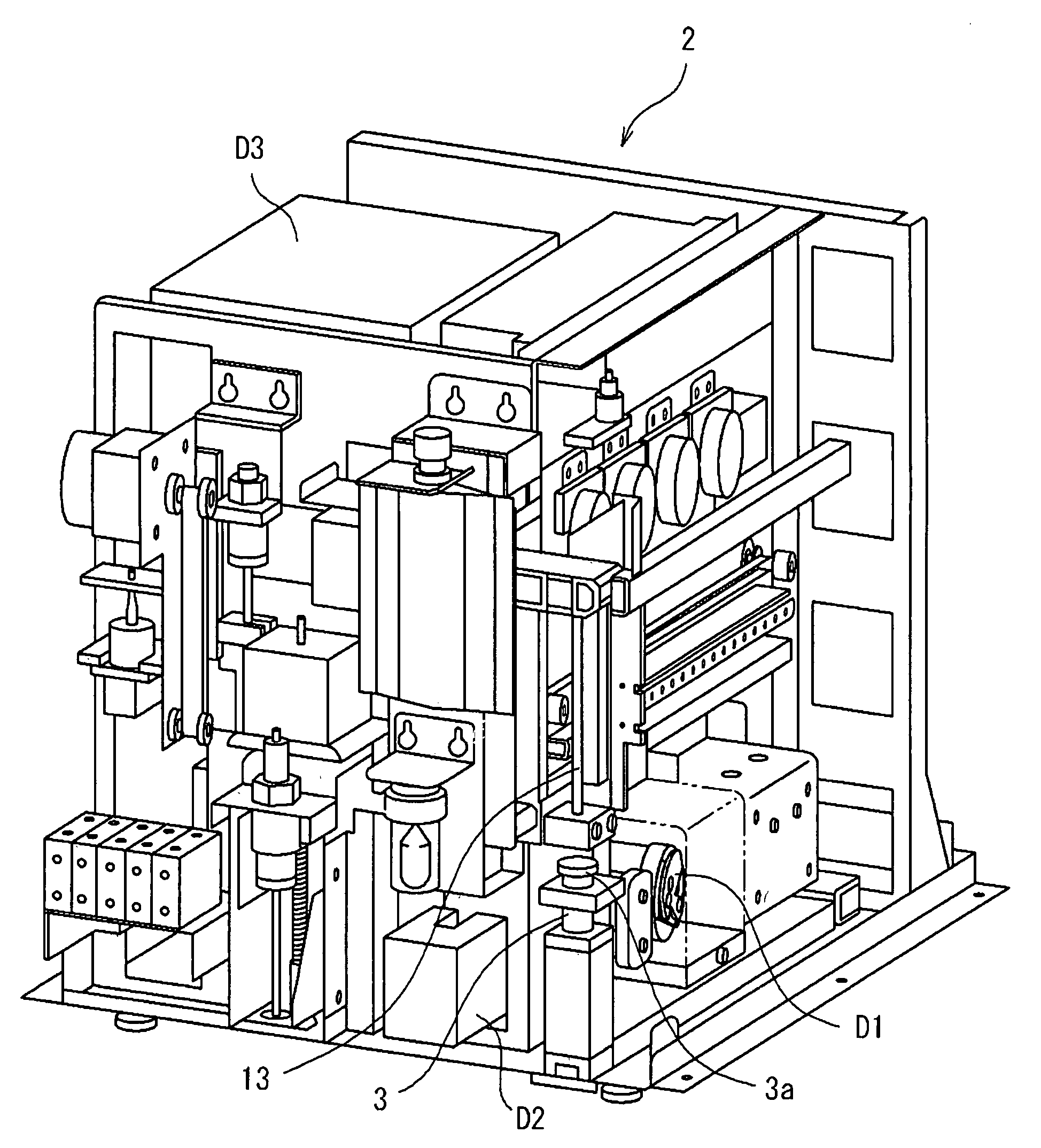
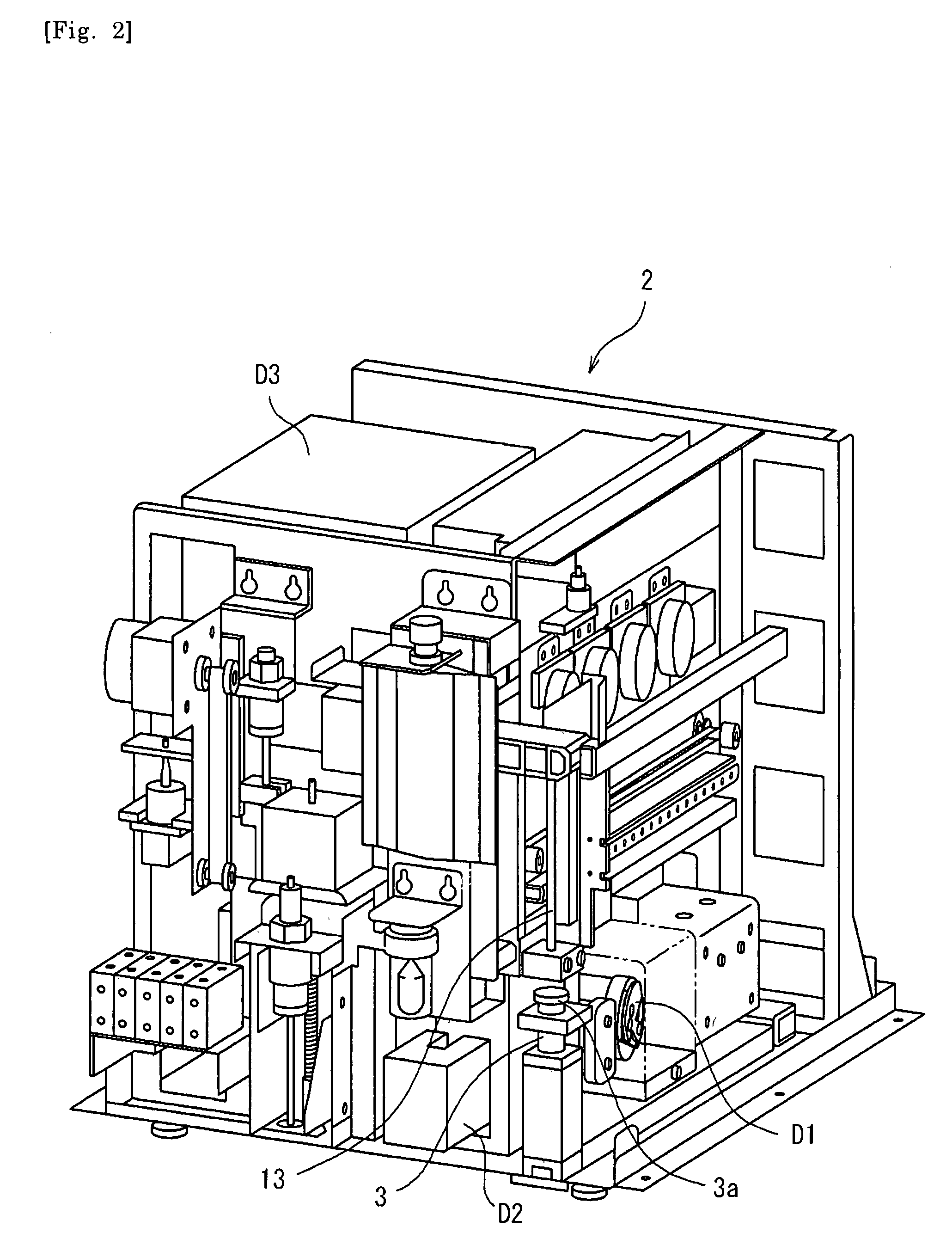
[0140]FIGS. 21 and 22 show Modified Examples of the measurement sections D1, D2 and D3. An optical measurement section D2 related to the modified example is configured as an electric and optical composite measurement unit. Additionally, unless otherwise specified herein, a sample measuring apparatus related to the modified example is the same as described in FIGS. 1 to 20.

[0141]This electric and optical composite measurement unit D2 is the one disclosed in Japanese Patent Laid-Open No. 7-128217. In other words, this composite measurement unit D2 integrally includes the functions of both of the electric measurement section D1 and optical measurement section D2 indicated in FIG. 4, and can perform measurements based on different measurement principles by means of a single measurement unit. Outputs of the composite measurement unit D2 of FIGS. 21 and 22 include an electric measurement output based on an electric measurement ...

example 2

[Modified Example 2 of the Measurement Sections D1, D2 and D3]

[0146]FIG. 23 indicates the modified example of the measurement sections D1, D2 and D3. The electric measurement section D1 related to the modified example is configured as an electric and optical composite measurement unit. Additionally, unless otherwise specified herein, a sample measuring apparatus related to the modified example is the same as described inFIGS. 1 to 20.

[0147]This electric and optical composite measurement unit D1 is also the one disclosed in Japanese Patent Laid-Open No. 7-128217. In other words, this composite measurement unit D1 integrally includes the functions of both of the electric measurement section D1 and optical measurement section D2 indicated in FIG. 4, and can perform measurements based on different measurement principles by means of a single measurement unit. Outputs of the composite measurement unit D1 of FIG. 23 include an electric measurement output based on an electric measurement fu...


PUM


Abstract

A sample measuring apparatus of measuring a component in a biological sample, comprising: an input section for inputting a sample species of a biological sample; a measurement sample preparation section for preparing a measurement sample by mixing the biological sample with a reagent; a first measurement section; a second measurement section being different from the first measurement section; a measurement sample supply section for supplying the measurement sample prepared in the measurement sample preparation section to at least one of the first measurement section and second measurement section; and a control section for controlling the measurement sample supply section based on the inputted sample species.

Description

RELATED APPLICATIONS[0001]This application claims priority under 35 U.S.C. §119 to Japanese Patent Application No. JP2006-094947 filed Mar. 30, 2006, the entire content of which is hereby incorporated by reference.FIELD OF THE INVENTION[0002]The present invention relates to a sample measuring apparatus and sample measuring method.BACKGROUND OF THE INVENTION[0003]Recently, as a pet boom spreads, apparatuses examining animals have been developed so as to be capable of coping with the sophistication of animal medications and various species of animals. In particular, in blood cell assay apparatuses of measuring blood cells in animal bloods, apparatuses capable of classifying blood cells as well as counting the number of blood cells and apparatuses capable of automatically changing measurement sensitivity adapting to the species of animals have been developed and used in many animal hospitals and animal experiment facilities.[0004]As such a blood cell assay apparatus, there exists a sam...

Claims


Application Information

Patent Timeline
IPC IPC(8): G01N33/00
CPCG01N1/38G01N15/12G01N15/1456G01N33/5094G01N33/80Y10T436/101666G01N35/00584G01N2015/0073G01N2015/0084G01N2015/0088G01N33/86
Inventor NAGAI, TAKAAKIMATSUMOTO, HIDEAKIHAMADA, YUICHI
Owner SYSMEX CORP
Why Eureka
Try Eureka