Ion implanter and method for controlling the same

a technology of implanters and implants, applied in the field of implanters and methods for controlling the same, can solve the problems of low dosage, increased load of calculation of pressure compensation factors ksub>a/sub>and k, and generated underdose phenomenon, etc., and achieves high dosage accuracy.

Inactive Publication Date: 2006-01-10
SENCORP
View PDF20 Cites 14 Cited by
  • Summary
  • Abstract
  • Description
  • Claims
  • Application Information

AI Technical Summary

Benefits of technology

[0065]According to the aspects and various modifications of the present invention described above, by performing simple adjusting operation be

Problems solved by technology

However, in the related ion implanter, the following two problems have occurred.
The first problem is an underdose (deficiency of dosage) phenomenon generated when the pressure in the vicinity of wafers i

Method used


Image

  • Ion implanter and method for controlling the same
  • Ion implanter and method for controlling the same
  • Ion implanter and method for controlling the same

Examples


Embodiment Construction

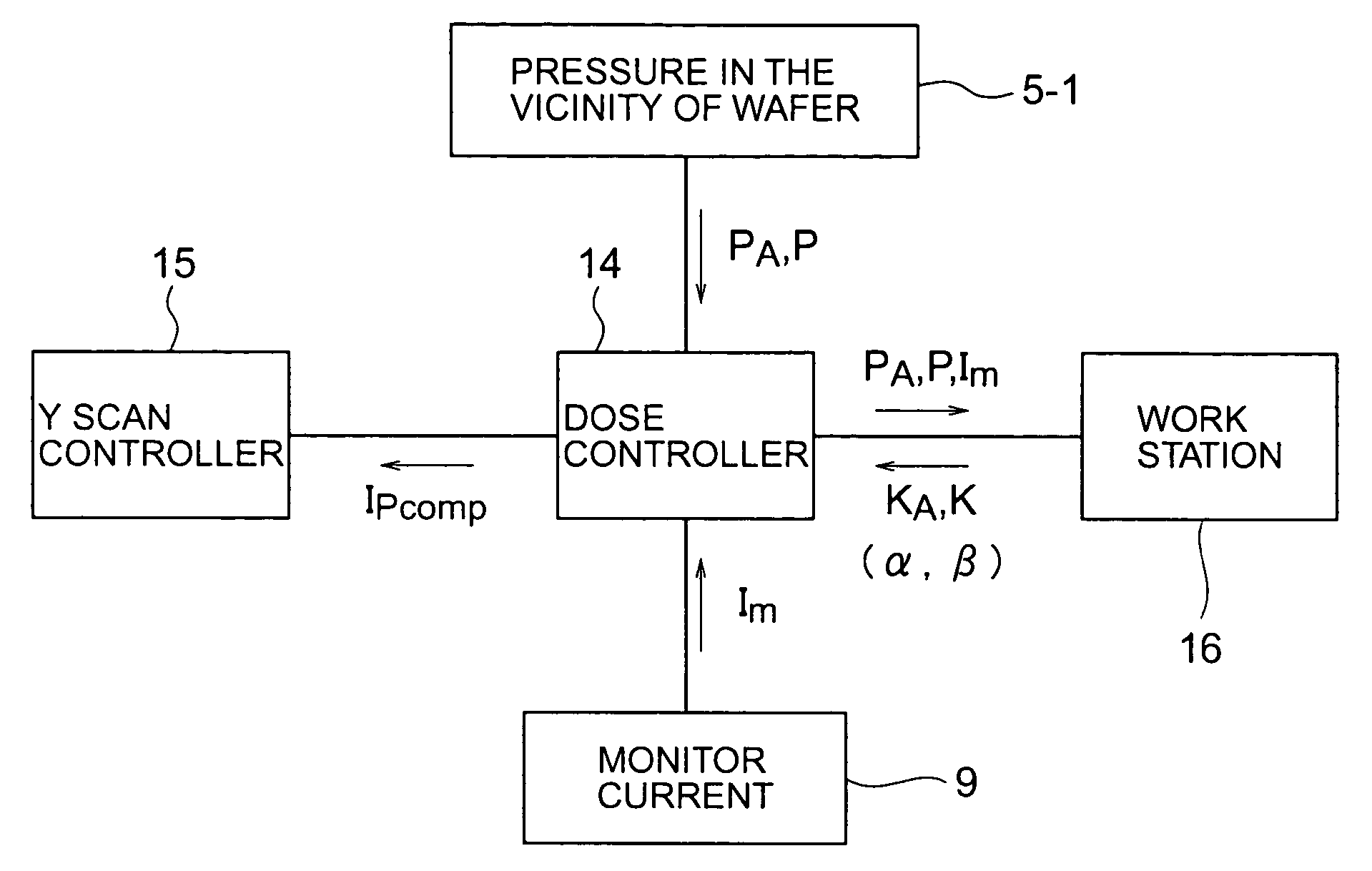
[0076]Referring to FIG. 3, the structure of a typical ion implanter used for the present invention will be described. Reference numerals 21, 22, and 23 indicate vacuum pumps provided for vacuum chambers 98, 99, and 100, respectively, for exhausting gases. Reference numeral 24 indicates a vacuum pump provided for an implantation process chamber 7 for exhausting gases. The traveling direction of an ion beam 2 emitted from an ion source 1 is deflected by a mass analysis electromagnet apparatus 3, and mass analysis is performed by a mass analysis slit 4. The ion beam 2 passing through the mass analysis slit 4 is implanted into a wafer 8 in the implantation process chamber 7. In addition, at the inlet of the mass analysis electromagnet apparatus 3, a partition plate 11 having an aperture used as an ion beam path is provided. In addition, in the vacuum chamber 100 located between the mass analysis slit 4 and the implantation process chamber 7, a plasma shower 6 is provided for suppressing...


PUM

PropertyMeasurementUnit
Pressureaaaaaaaaaa
Densityaaaaaaaaaa
Electrical conductanceaaaaaaaaaa

Abstract

The present invention is applied to an ion implanter provided with a vacuum pressure compensation mechanism. The pressure compensation mechanism samples measured beam currents and vacuum pressures in the vicinity of wafers in preliminary implantation and stores function parameters in a memory unit which are obtained by calculating parameters of a predetermined function by fitting the relationship between the measured beam currents and the vacuum pressures. In actual implantation, the pressure compensation mechanism corrects the measured beam current using the function parameters stored as a function of the vacuum pressure, and based on the corrected beam current, the dosage control is performed. In the present invention, an actual beam loss is compensated for based on the estimation from a pressure in the vicinity of the wafers in a region downstream of a mass analysis slit.

Description

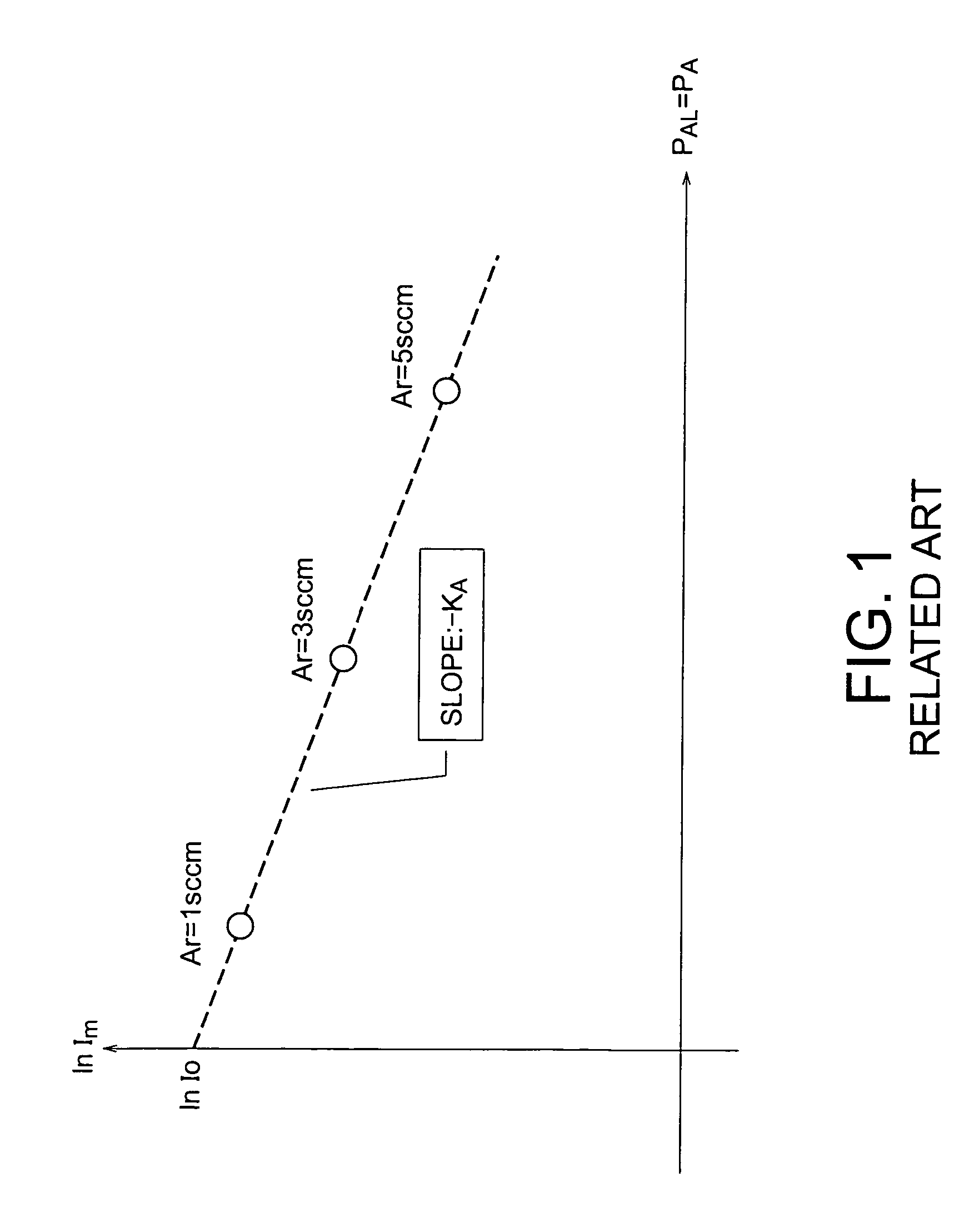
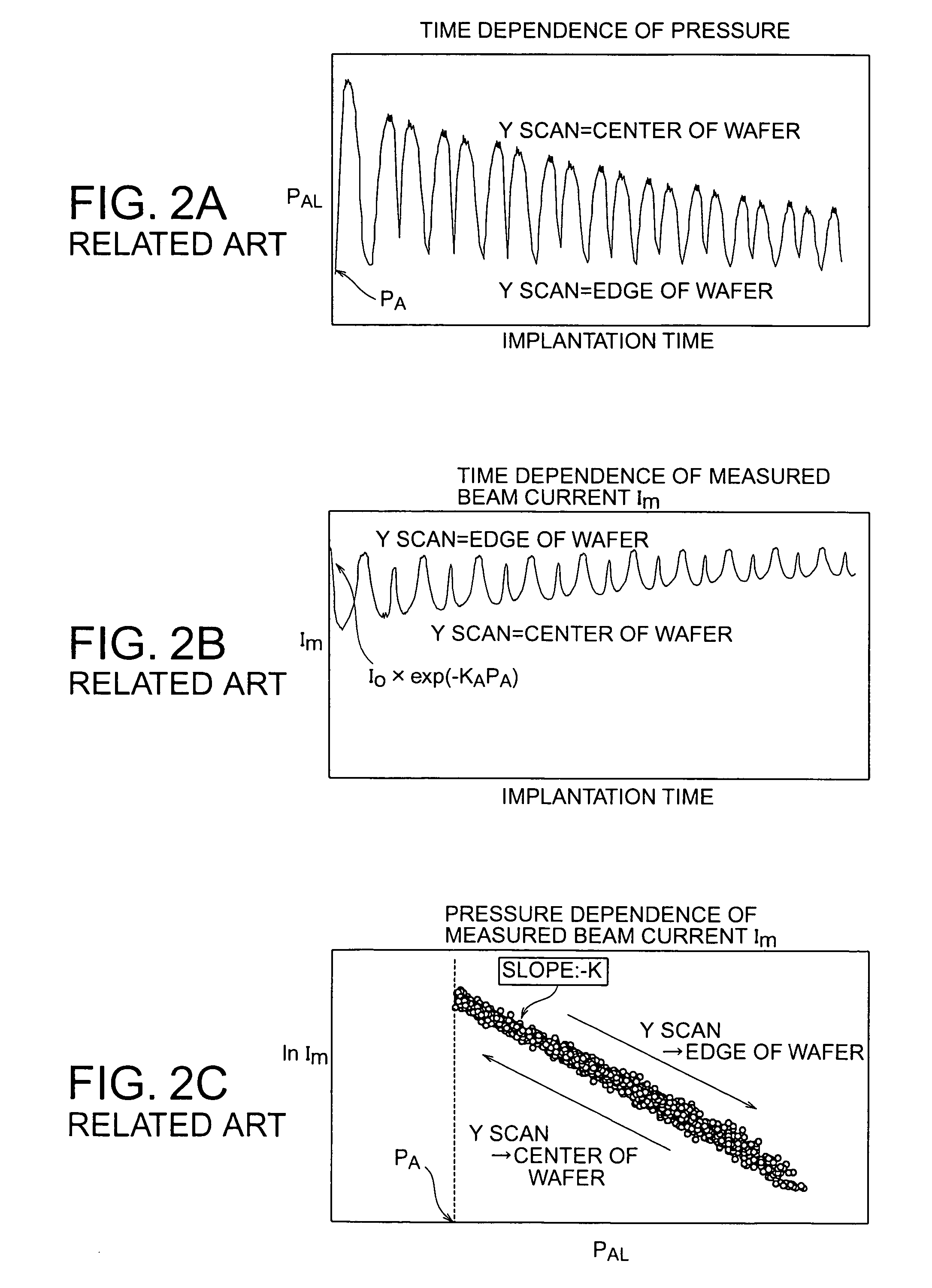
[0001]The present application claims priority to prior Japanese patent application JP 2003-166459 filed on Jun. 11, 2003, the disclosure of which is incorporated herein by reference.BACKGROUND OF THE INVENTION[0002]The present invention relates to ion implanters and methods for controlling the same.[0003]Ion implanters have been used in a process for manufacturing semiconductor integrated circuits and are able to implant impurities into finely defined regions on a surface of a semiconductor substrate with good accuracy. In the ion implanters described above, an implanting amount (dosage) of impurity ions per unit area is generally obtained by conversion of an ion beam current I detected by a Faraday cup provided at the rear side of wafers. That is, the number N of ions implanted per unit time is represented by the following equation (1).N=I / q(namely, I=q·N)  (1)[0004]In this equation (1), q indicates the charge per one ion.[0005]In actual ion implantation, by collision of ions with ...

Claims


Application Information

Patent Timeline
IPC IPC(8): H01J37/304H01J37/317C23C14/48H01J37/18H01L21/265
CPCH01J37/304H01J37/3171H01J2237/31703
Inventor SANO, MAKOTOSUGITANI, MICHIROKABASAWA, MITSUAKITSUKIHARA, MITSUKUNI
Owner SENCORP
Why Eureka
Try Eureka