Leg brace for stilts

Inactive Publication Date: 2007-10-04
LIN JOE
View PDF14 Cites 10 Cited by
  • Summary
  • Abstract
  • Description
  • Claims
  • Application Information

AI Technical Summary

Benefits of technology

[0009] Prior art stilt leg braces were formed of metal from expensive extrusion and bending processes. They were subject to metal fatigue, stress cracking, and possible failure when in use. They were also lacking in comfort for the user, sh

Problems solved by technology

They were subject to metal fatigue, stress cracking, and possible failure when in use.
They were also lacking in

Method used


Image

  • Leg brace for stilts
  • Leg brace for stilts
  • Leg brace for stilts

Examples


Embodiment Construction

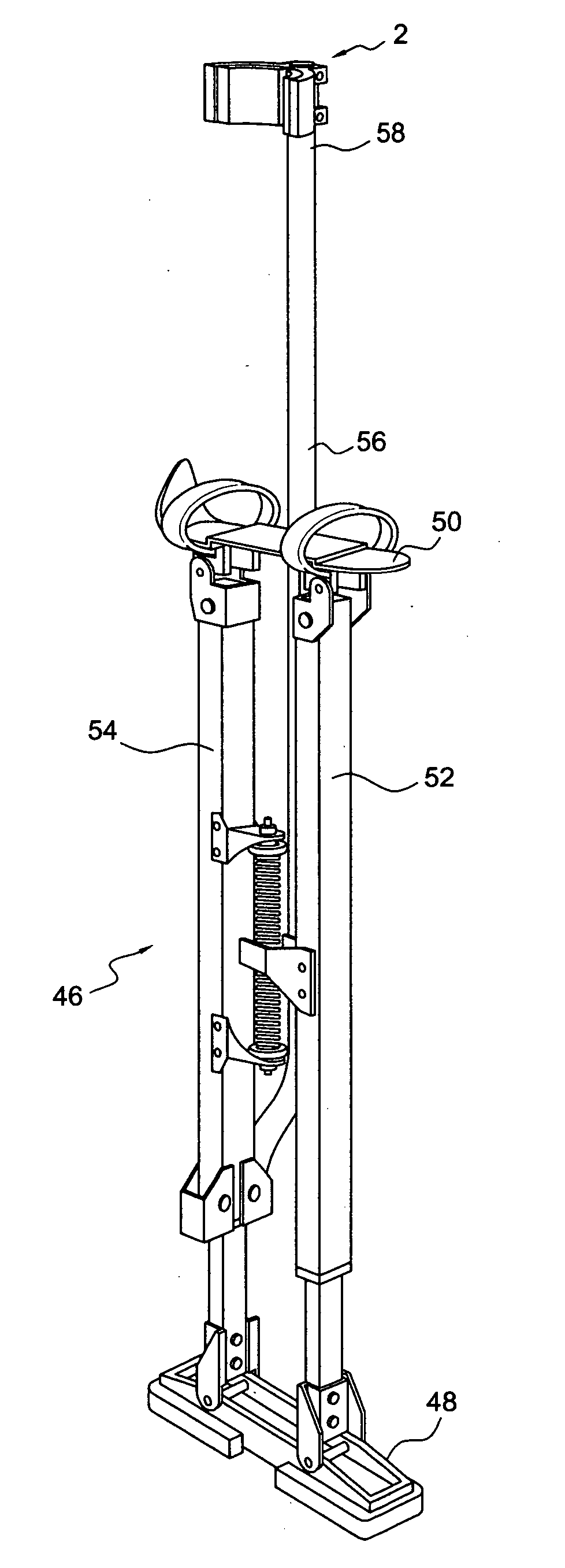
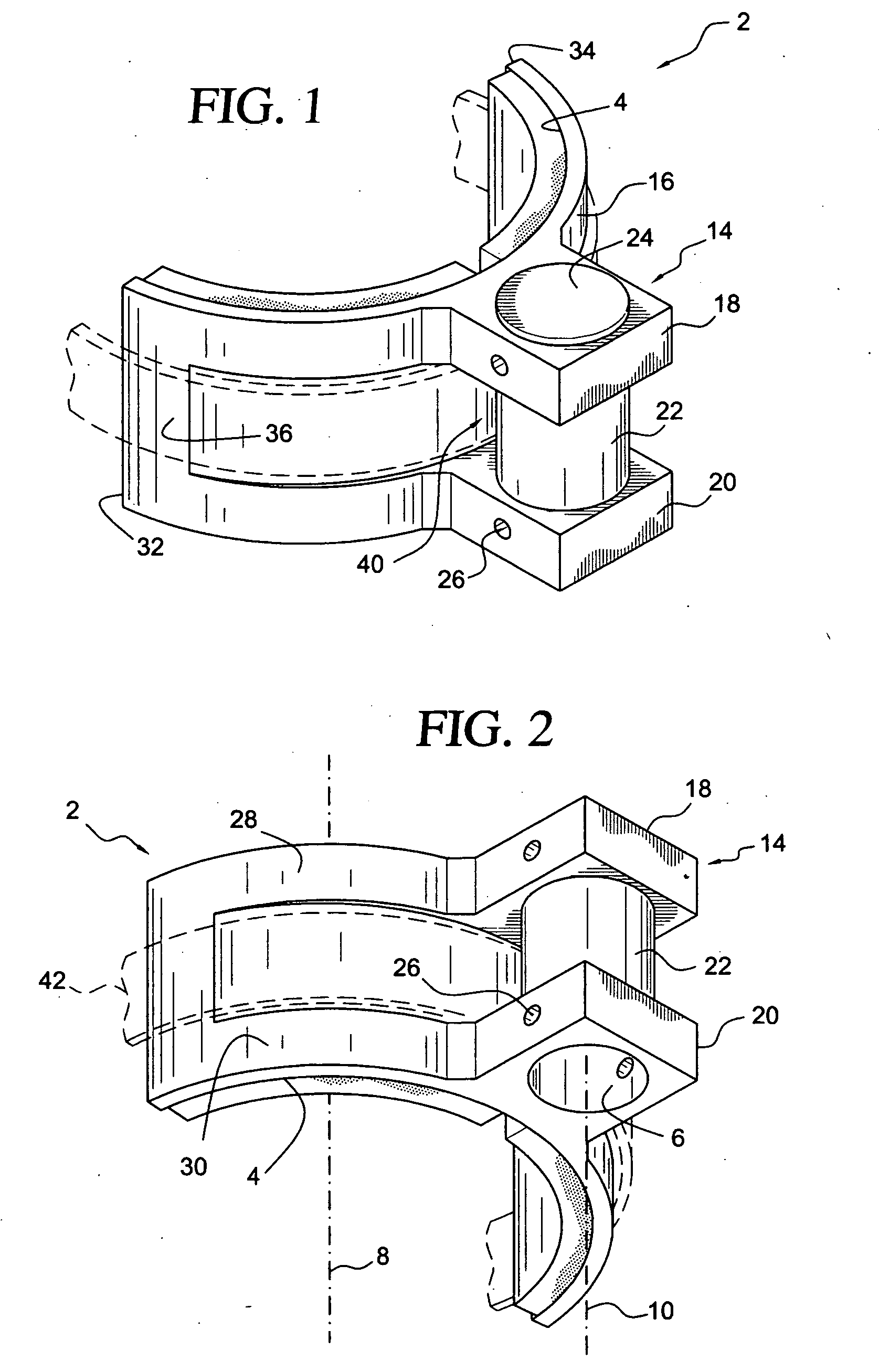
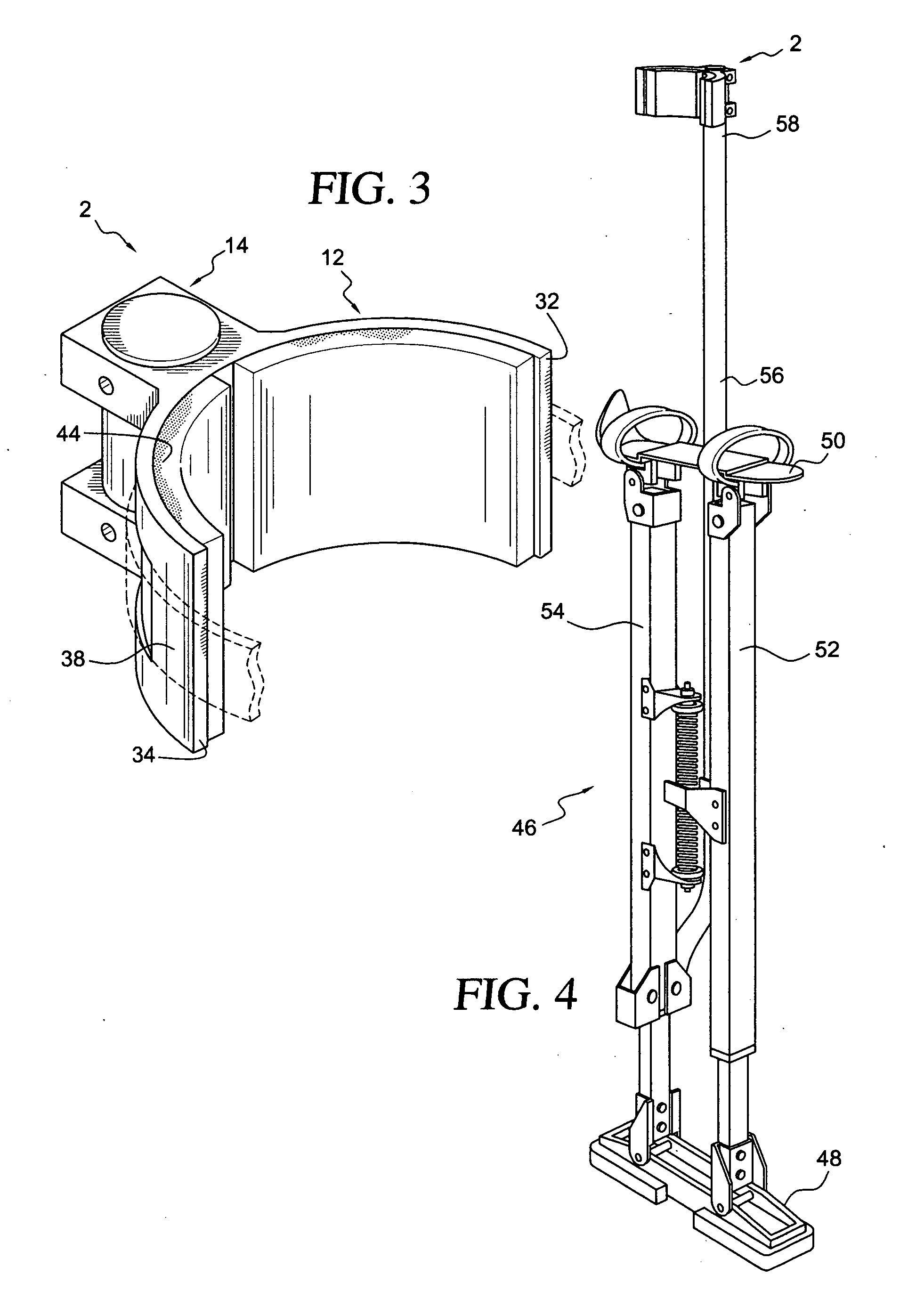
[0014] With reference to FIGS. 1 and 2, there is shown a non-metallic unitary leg brace element 2 for a stilt. The leg brace element comprises a plastic body. The plastic body defines a generally semi-cylindrical concave inside surface 4 for supporting a stilt user's leg, and a passage 6 spaced apart from the generally semi-cylindrical concave inside surface for receiving a leg support of the stilt.

[0015] A wide range of plastic material is suitable for construction of the brace element 2. For cost and speed of production, a thermoplastic would be preferred. For strength, a fiber reinforced thermoplastic would be preferred. For durability, an engineering thermoplastic would be preferred. Short glass fiber reinforced polyetheretherketone (PEEK) is a suitable material, for example. The brace element 2 is preferably produced by an injection molding process.

[0016] The generally semi-cylindrical concave inside surface is positioned around a longitudinal axis 8. A longitudinal axis 10 o...


PUM


Abstract

A plastic leg brace element for construction stilts is disclosed. The leg brace element comprises a plastic body. The plastic body defines a generally semi-cylindrical concave inside surface for supporting a stilt user's leg, and a passage spaced apart from the generally semi-cylindrical concave inside surface for receiving a leg support of the stilt.

Description

FIELD OF THE INVENTION [0001] The invention relates to an improved leg brace for a stilt, particularly stilts employed in the construction industry to facilitate overhead work, such as accessing and hanging suspended ceiling structures or overhead electrical or duct work. BACKGROUND OF THE INVENTION [0002] U.S. Pat. No. 5,645,515, the disclosure of which is incorporated by reference herein, is an example of one type of stilt employed by the construction industry. It utilizes a single upright post extending above the shoe platform and having a calf brace near the upper end to provide stability to the user. The calf brace attaches to the side of the post and is solely dependent on the retention of the fasteners for safety. [0003] The calf brace in this disclosure is constructed of metal and is expensive to produce. A calf brace that could be produced in one step would be less labor intensive and less expensive. [0004] Also, metallic calf braces are subject to fatigue cracks over time,...

Claims


Application Information

Patent Timeline
IPC IPC(8): A63B25/00
CPCA63B25/00
Inventor LIN, JOE
Owner LIN JOE
Why Eureka
Try Eureka