
Device for massaging feet and calves

Active Publication Date: 2007-10-04
YU CHUN CHIEN
View PDF11 Cites 17 Cited by
  • Summary
  • Abstract
  • Description
  • Claims
  • Application Information

AI Technical Summary

Benefits of technology

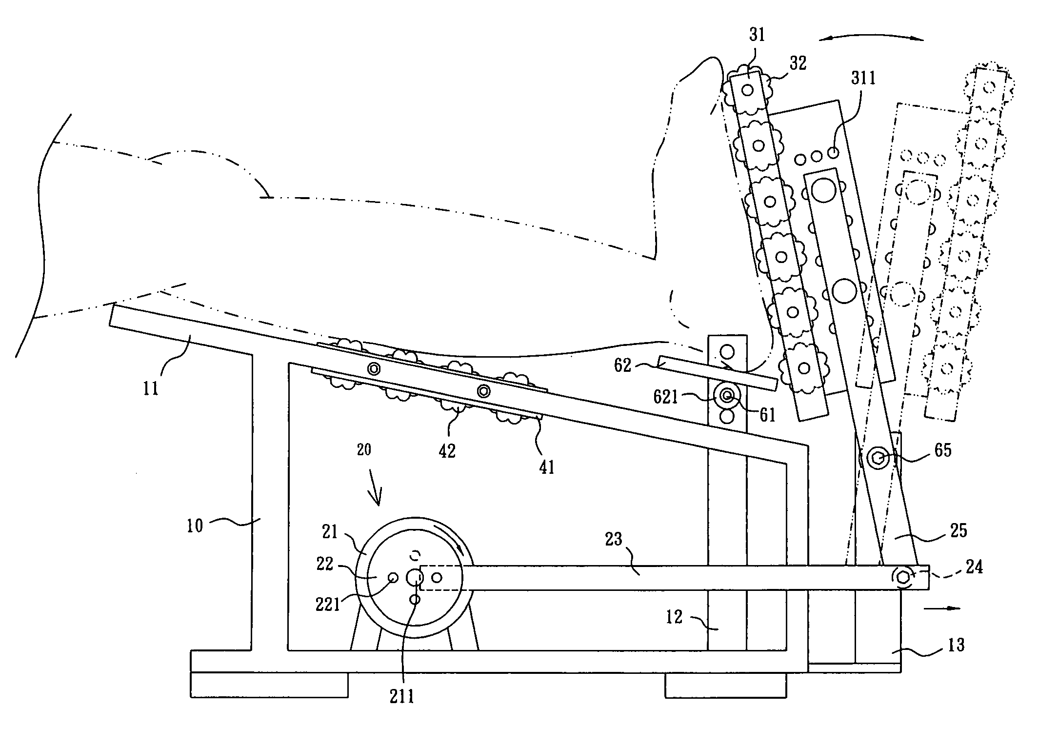
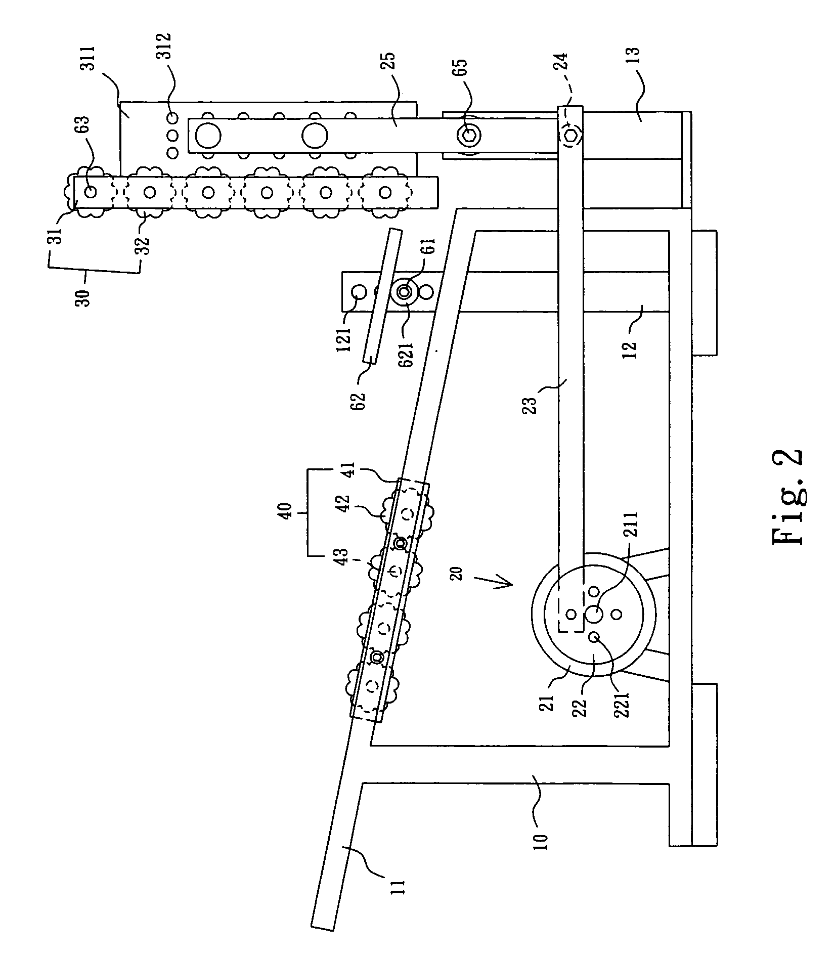
[0006] It is therefore an object of the present invention to provide a massage device comprising a frame including a top board mounted on legs, two side posts proximate a front end, each post having a plurality of upper first holes disposed vertically, and a support extended forward from the front end; a drive unit provided below the board and including a motor, a flywheel mounted on one end of a rotating shaft of the motor, a connecting rod having one end connected to the flywheel, a transverse bar mounted in the support and having one end pivotably connected to the other end of the connecting rod, and an arm having a lower end pivotably connected to the other end of the connecting rod and a pivot portion above its lower end pivotably connected to an upper portion of the support; a feet massage unit including a first frame element, a brace plate extended forward from the first frame element, the brace plate including a plurality of sets of second holes wherein an upper portion of the arm is mounted at the sets of second holes, and two parallel sets of first rollers, each set of the first rollers being electrically connected to the motor and mounted across both sides of either half of the first frame element; a calf massage unit mounted on the board and including a second frame element, and a plurality of transverse second rollers electrically connected to the motor and mounted across both sides of the second frame element; and a transverse plate member including two underside side cylinders, and a pin adapted to insert into the cylinders and through the first hole for releasably fastening; whereby resting the calves of a person on the second rollers, contacting bottoms of the feet with the first rollers, resting the ankles on the plate member, and powering on the drive unit will rotate the first and second rollers to massage the calves and the bottoms of the feet and relieve pain on nerve centers in the parts of the legs below the knees with the foot massage unit reciprocated.
[0007] In one aspect of the present invention the calves are adapted to rest on two top ones of the first rollers such that powering on the drive unit will rotate the top ones of the first rollers to massage the calves and relieve pain on nerve centers in the calves with the foot massage unit reciprocated.

Problems solved by technology

But this is unsatisfactory for the purpose for which the invention is concerned for the following reasons: The massage device is designed to massage foot bottom only.
Further, the standing is not stable.
Thus, the person may fall from the device if sufficient care is not taken during the massage.
Furthermore, the massage device is unable to relieve pain on nerve centers in the parts of the legs below the knees.

Method used


Image

  • Device for massaging feet and calves
  • Device for massaging feet and calves
  • Device for massaging feet and calves

Examples


Embodiment Construction

[0016] Referring to FIGS. 2 to 7, a massage device in accordance with a preferred embodiment of the invention comprises a frame 10, a drive unit 20, a feet massage unit 30, and a calf massage unit 40. Each component is discussed in detailed below.

[0017] The frame 10 comprises a top board 11 disposed above a supporting ground by a predetermined distance, two side posts 12 proximate its front end, each post 12 having a plurality of upper holes 121 disposed vertically, and a support 13 extended forward from the front end.

[0018] The drive unit 20 is provided on a bottom of the frame 10 below the board 11. The drive unit 20 comprises a motor 21, a flywheel 22 mounted on one end of a rotating shaft 211 of the motor 21 and including four lateral holes 221 provided peripherally relative to the rotating shaft 211, a connecting rod 23 having one end connected to one of the holes 221, a transverse bar 24 mounted in the support 13 and having one end pivotably connected to the other end of the...


PUM


Abstract

A massage device includes a frame including a top board, a support plate, and a forward support; a drive unit including a rod interconnected a motor driven flywheel and a transverse bar in the support, and a pivotal arm having a lower end pivotably connected to the bar; a feet massage unit including a forward brace plate releasably secured to an upper portion of the arm; and a calf massage unit mounted on the board. Resting the calves on rollers of the calf massage unit, contacting bottoms of the feet with rollers of the feet massage unit, resting the ankles on the support plate, and powering on the drive unit will rotate the rollers to massage the calves and the bottoms of the feet and relieve pain on nerve centers in the parts of the legs below the knees with the foot massage unit reciprocated.

Description

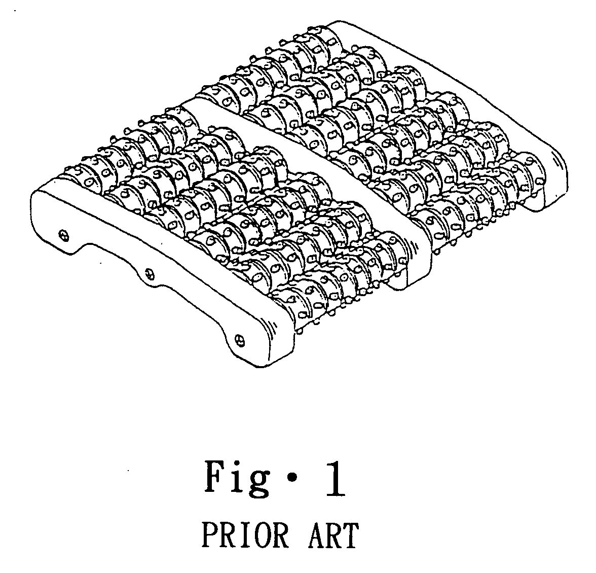
BACKGROUND OF THE INVENTION [0001] 1. Field of Invention [0002] The present invention relates to massage equipment and more particularly to a device capable of massaging feet and calves and relieving pain on nerve centers in the parts of the legs below the knees. [0003] 2. Related Art [0004] A wide variety of massage devices are commercially available. For example, a conventional foot massage device is shown in FIG. 1. As illustrated, five rows of rollers are mounted between a left frame element and a central frame element and five rows of rollers are mounted between a right frame element and the central frame element respectively. In use, a person stands on the massage device and walks thereon. As such, the rollers roll to massage bottoms of the feet. [0005] But this is unsatisfactory for the purpose for which the invention is concerned for the following reasons: The massage device is designed to massage foot bottom only. Further, the standing is not stable. Thus, the person may fa...

Claims


Application Information

Patent Timeline
IPC IPC(8): A61H7/00
CPCA61H7/001A61H2015/0014A61H2205/10A61H2201/1284A61H2203/0456A61H2015/0035A61H15/00A61H2201/1695
Inventor YU, CHUN-CHIEN
Owner YU CHUN CHIEN
Learn More