Fluid jet print module

a printing module and fluid jet technology, applied in printing and other directions, can solve the problems of non-uniform or misdirected jets, differences in etch depths, and non-uniform edges

Inactive Publication Date: 2007-10-11
PICOSYS
View PDF19 Cites 7 Cited by
  • Summary
  • Abstract
  • Description
  • Claims
  • Application Information

AI Technical Summary

Problems solved by technology

Furthermore, since nozzles are usually made by etching a groove or u-channel into one plate and bonding it to a second plate, two factors can have a significant impact on their shape and size: a) the etch rate of materials or etch tools can vary significantly, leading to differences in etch depths; and b) the interfaces and the defining nozzle edges can vary in shape during the bonding process of the plate, leading to nonuniform edges and subsequently to non-uniform or misdirected jets.
The disadvantage is that such a module can not be slanted in order to increase resolution, but can only be interlaced.
However, this approach generally gives rise to secondary deleterious problems associated with: a) the materials used to fabricate the nozzle plates; and b) the adhesives used to attach the nozzle plate to the print module body.
The main difficulty with the materials used to fabricate such nozzles plates is their chemical incompatibility with the variety of fluids to be jetted.
In addition, adhesives suffer from a lack of robustness / strength against solvents or extreme pH values.
Adhesives also swell and cause the characteristics of the nozzle to change with time and eventually to fail.
2. nozzles that are created by affixing two plates have inherently sharp corners, and therefore are not round or are non-uniform;
3. the use of a special nozzle plate or other design feature leads to problems arising from chemical incompatibility of the materials used with the variety of fluids to be jetted (e.g. inks), or requires the use of adhesives;
5. the design is bulky, complicated, difficult or costly to manufacture, or subject to failure during routine use.

Method used


Image

  • Fluid jet print module
  • Fluid jet print module
  • Fluid jet print module

Examples


example 1

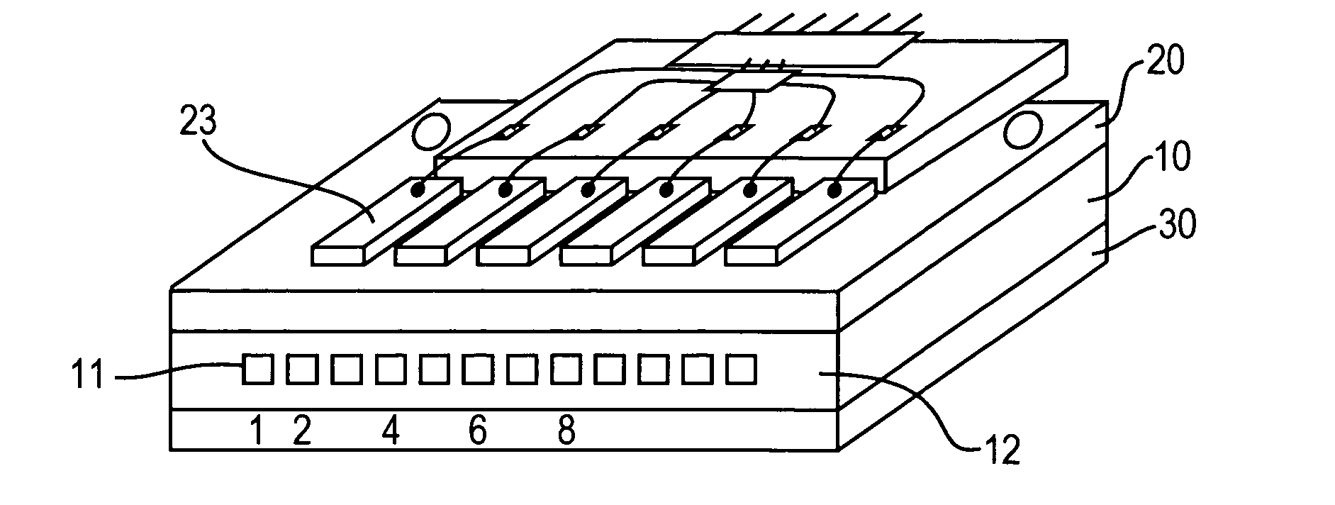
[0070] The print module is composed of three structured components: a nozzle-carrying member (10) embedded between two chamber-carrying side members (20) and (30), as illustrated in FIGS. 1 to 7). The nozzle face (12) of the nozzle-carrying member (10) carries the nozzles (11), which are built in one row in the center of the nozzle-carrying member as shown in FIG. 1. The total number of nozzles is usually 2n, where n is an integer, but could be any other number as well.

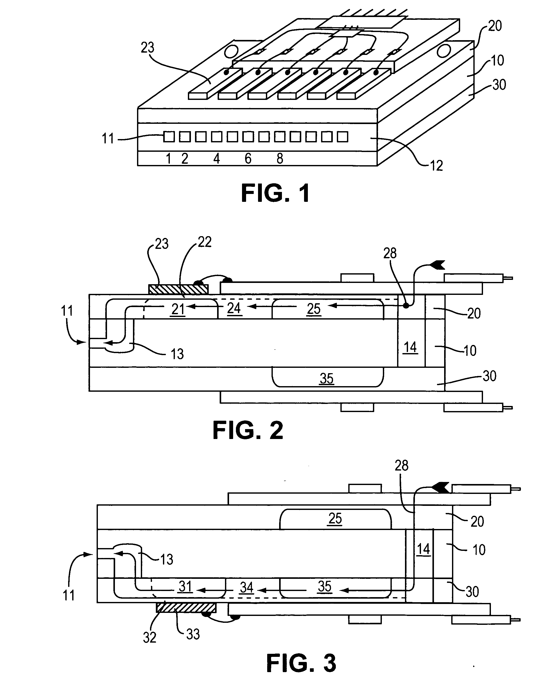
[0071]FIGS. 2 and 3 show the fluid paths of the print module. The embedded nozzles (11) are connected to wells (13) in the nozzle-carrying member (10). The wells are structured on both sides of the nozzle-carrying member in an alternating and opposing pattern with respect to the nozzles, the even numbered nozzles form one nozzle group connecting to wells facing the top side chamber-carrying member (20), as shown in FIG. 2, and the odd numbered nozzles form a second nozzle group connecting to wells facing the bottom s...

example 2

[0082] The print module is composed of five components: a nozzle-carrying member (10) embedded between two chamber-carrying side members (20) and (30), each of the side members being composed of one chamber plate (20a) and (30a) respectively, and one capping plate (20b) and (30b) respectively, as illustrated in FIGS. 8 to 10.

[0083] The nozzles (11) are disposed in the face center of the nozzle-carrying member composed of a nozzle plate. The chambers of this device are etched through in chamber plates (20a) and (30a) in an alternating top-bottom pattern, respectively, whereas the diaphragms are provided two thin cover plates (20b) and (30b). The wells are structured on both sides of the nozzle-carrying member (10) in an alternating pattern with respect to the nozzles, the even numbered nozzles connecting to wells facing the top side member (20), as shown in FIG. 9, and the odd numbered nozzles connecting to wells facing the bottom side member (30), as shown in FIG. 10. The wells (13...

example 3

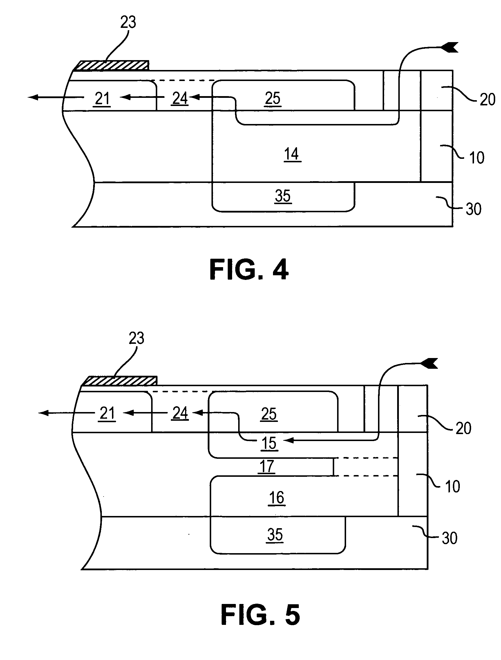
[0085] The print module is composed of three components: a nozzle- and chamber-carrying member (10) embedded between two side members (20) and (30), as illustrated in FIGS. 11 to 13. The entire channel structure of this device is built into a single plate (10). The nozzles (11) are centrally disposed in the nozzle face (12) of the center member. The chambers (21), (31), the wells (13) and the manifolds (15), (16) are build on both sides of the center member. The two side members (20) and (30) are cover plates providing the chamber diaphragms (22) and (32) and covering the manifolds (15) and (16), as shown in FIGS. 12 and 13, respectively. The fluid supply is provided by the two manifolds (15) and (16) separated from each other by a diaphragm (17). A fluid supply built out of one manifold (18), as depicted in FIG. 4, is also possible.

[0086] All other structural elements can be similar to those described in Example 1.


PUM


Abstract

A print module having nozzles which are centrally disposed in a nozzle face of the module is disclosed. The arrangement of the nozzles is symmetric with respect to fluidic paths in the nozzle plates or chamber plates. The connecting channels between chambers and nozzles can also be symmetric, allowing improved performance and uniformity of drop formation, drop size and drop velocity. The module does not suffer from fluid path differences between chamber plates, uses materials similar to the completed print module without the use of bonding agents such as adhesives, and greatly improves the jetting quality by using uniform or symmetric nozzles. In addition, the print module is slim, flat, robust, and can be slanted in order to increase resolution. A variety of fluids may be dispensed by the print module, including ink. The nozzles and nozzle arrangements in the print module can be made using advanced laser structuring.

Description

FIELD OF THE INVENTION [0001] This invention generally relates to a print module formed from a number of structured, flat plates bonded together to make a fluidic print module including, for example, print modules made according to the “piezo-planar side-shooter” principle. The modules are equipped with planar piezoelectric actuators to eject a fluid (usually ink) through a plurality of nozzles or a single nozzle and can have electronic driving circuitry remote to the print module or attached to the print module. More specifically, this invention relates to print modules formed with a particular nozzle structure and a method for forming such structure using advanced laser-assisted material structuring techniques. BACKGROUND OF THE INVENTION [0002] Print modules of the of the type described herein are used in digital printing machines, material deposition tools like office printers, wide format printers, franking or addressing machines, labeling machines, three-dimensional model prin...

Claims


Application Information

Patent Timeline
Patent Type & Authority Applications(United States)
IPC IPC(8): B41J2/14
CPCB41J2002/14491B41J2/14233
Inventor KARAM, RAY M. IIROUSSOS, GEORGES
Owner PICOSYS
Why Eureka
Try Eureka