

Objective lens
a technology of objective lenses and lenses, applied in the field of objective lenses, can solve problems such as negative influences in regard
Active Publication Date: 2007-10-11
CARL ZEISS SMT GMBH
View PDF5 Cites 2 Cited by
- Summary
- Abstract
- Description
- Claims
- Application Information
AI Technical Summary
Benefits of technology
[0012] It is an object underlying the invention to improve an objective lens of the type specified at the outset such that the afore-specified disadvantages are avoided. In particular, the objective lens shall not cause a variation of the image angle during focusing, i.e. the object-sided image angle shall remain constant at a given image height for all distances to an object, without having negative implications on the possibility to correct the objective lens.
[0014] The object underlying the invention is thus entirely solved. By placing a focusing group into the rear portion of the objective lens, it is achieved in a surprisingly simple manner that an objective lens is created that may be corrected easily and that has no variation of the image angle during focusing.
Problems solved by technology
The prior art objective lenses of the type specified before, have the disadvantage that due to the positioning of the moved focus group in front of the iris diaphragm negative influences occur with regard to the correction of the objective lens.
Method used
View moreImage
Smart ImageViewing Examples

Examples
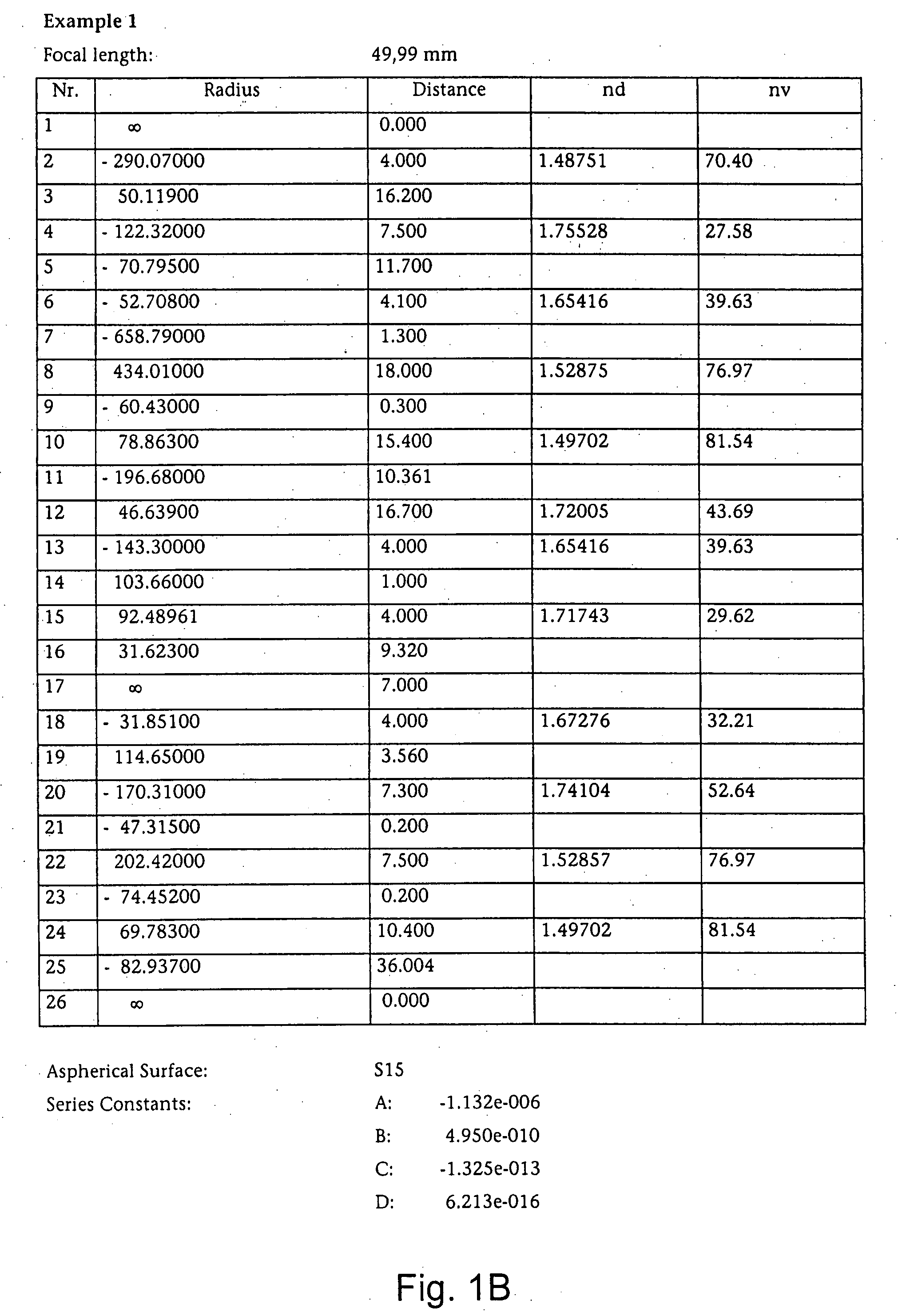
example 1
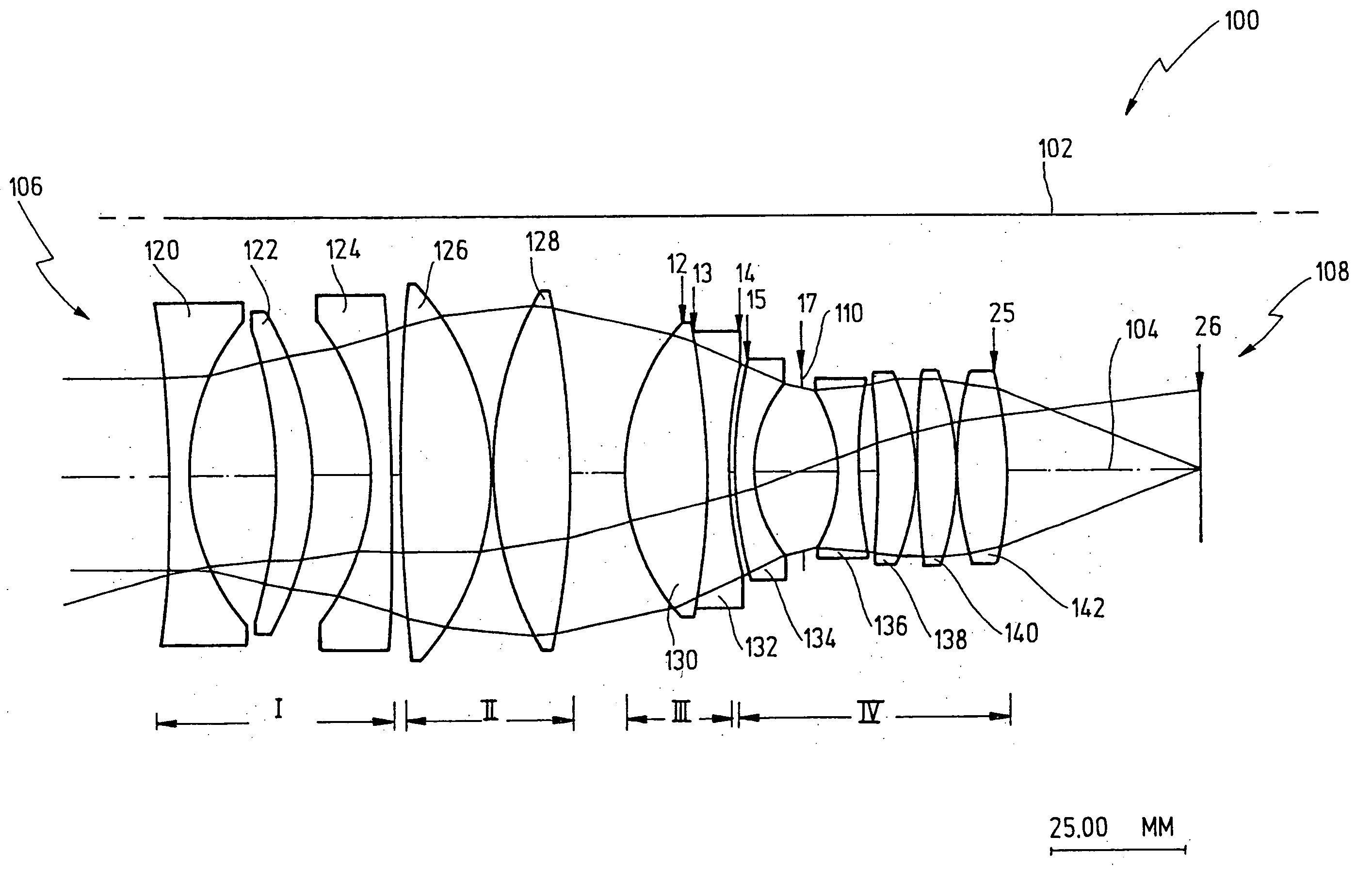
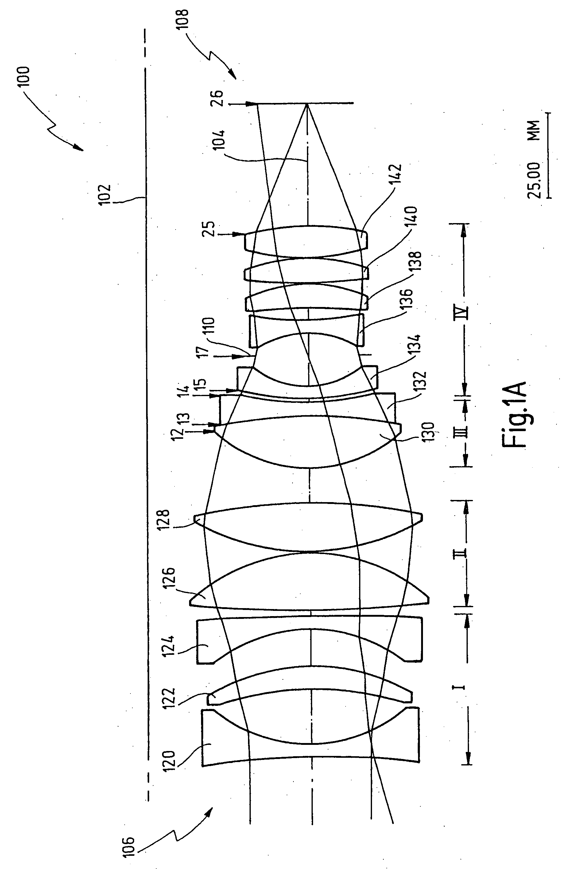
FIGS. 1A und 1B
[0057]
Lensf′(∞) / (1 − f′(e) *Groupβ(e)f′(e)β(e) / APF)Δ / %I0.00049.98949.9890.000II0.02749.61549.3660.503III0.05949.14748.6710.978IV0.14247.83447.0101.753
example 2
FIGS. 2A und 2B
[0058]
Lensf′(∞) / (1 − f′(e) *Groupβ(e)f′(e)β(e) / APF)Δ / %I0.00065.00065.0000.000II0.07464.52364.1690.551III0.12564.21663.6120.950
example 3
FIGS. 3A und 3B
[0059]
Lensf′(∞) / (1 − f′(e) *Groupβ(e)f′(e)β(e) / APF)Δ / %I0.00074.98574.9850.000II0.01574.59974.2370.488III0.04073.94073.0861.169IV0.11271.92670.0512.677
Login to View More PUM
 Abstract
An objective lens comprises a housing, an iris diaphragm and a plurality of lens groups. For focusing the objective lens while minimizing the variation of the image angle at least two lens groups are adapted to be moved relative to the housing. The one lens group is arranged in front of the iris diaphragm. The other lens group is arranged at least partially behind the iris diaphragm.
Description
CROSS-REFERENCE TO RELATED APPLICATIONS [0001] This application is a continuation of International Patent Application PCT / EP2005 / 009484, filed on Sep. 3, 2005 and published in German language, which international patent application claims priority from German Patent Application No. 10 2004 043 611.8, filed Sep. 7, 2004; German Patent Application No. 20 2004 020 515.7, filed Sep. 7, 2004 and German Patent Application No. 10 2005 025 204.4, filed May 25, 2005. The disclosures of the above applications are incorporated herein by reference.FIELD OF THE INVENTION [0002] The present invention is related to the field of objective lenses. [0003] More specifically, the invention is related to objective lenses in which no variation of the image angle occurs during focusing. [0004] Still more specifically, the invention is related to an objective lens having a housing, an iris diaphragm and a plurality of lens groups, wherein for focusing the objective lens while minimizing the variation of th...
Claims
Login to View More Application Information
Patent Timeline
 Patent Type & AuthorityApplications(United States)
IPC IPC(8): G02B15/14
CPCG02B15/177G02B13/04G02B9/34
InventorKLEIN, JUERGENNOFFKE, JUERGENGAENGLER, DIETMAR
OwnerCARL ZEISS SMT GMBH