Surgical Device for Anterolateral and Posterolateral Reconstruction

Inactive Publication Date: 2007-10-11
MCGUIRE DAVID A
View PDF27 Cites 9 Cited by
  • Summary
  • Abstract
  • Description
  • Claims
  • Application Information

AI Technical Summary

Benefits of technology

[0006] The present invention as embodied is directed to a surgical device and method of using the surgical device, referred to as an isometer, for restoring rotary and anterior or posterior knee stability when used in combination with an intra-articular ACL or PCL

Problems solved by technology

The isometer eliminates the variables in “free hand” determination and restoration of latera

Method used


Image

  • Surgical Device for Anterolateral and Posterolateral Reconstruction
  • Surgical Device for Anterolateral and Posterolateral Reconstruction
  • Surgical Device for Anterolateral and Posterolateral Reconstruction

Examples


Embodiment Construction

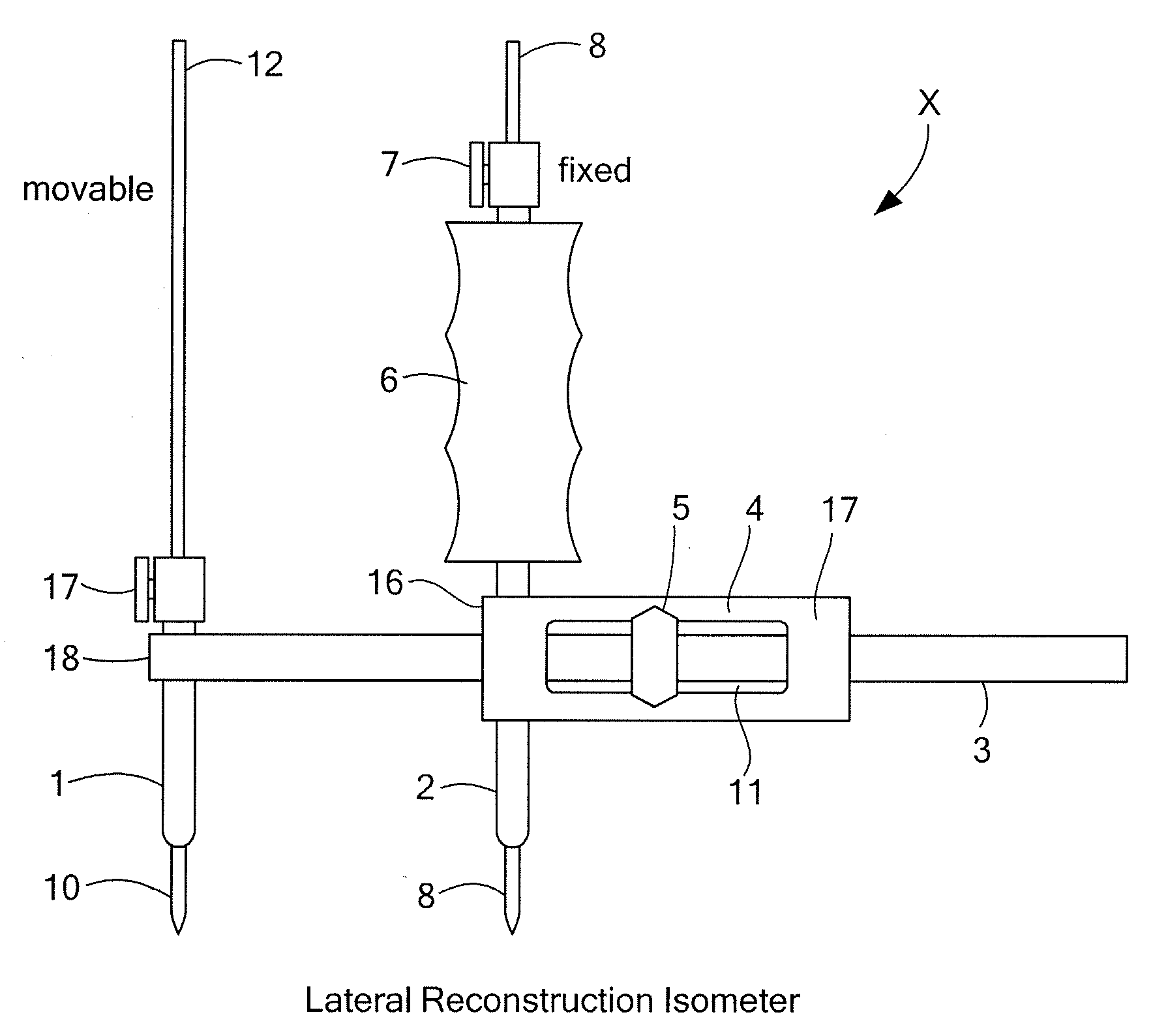
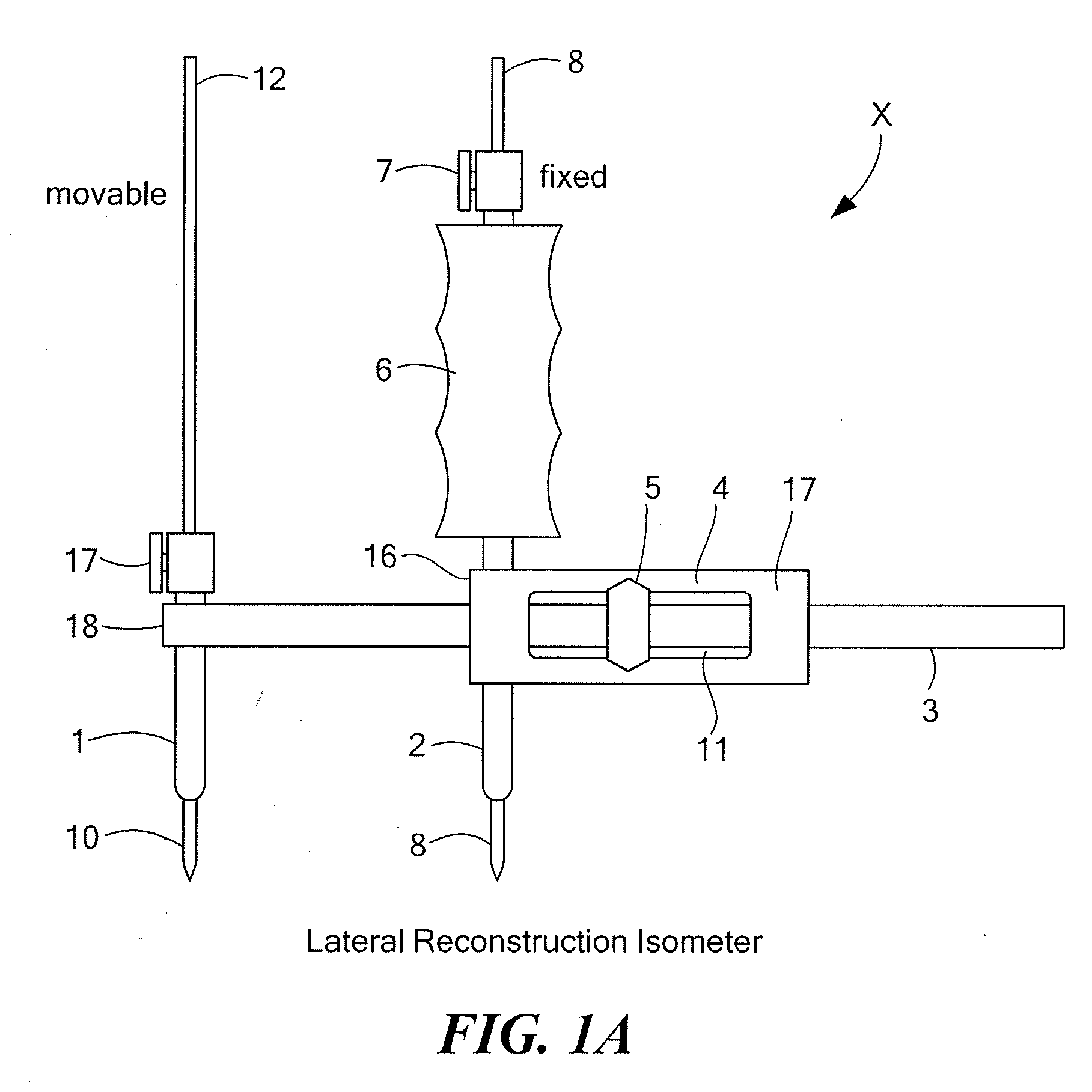
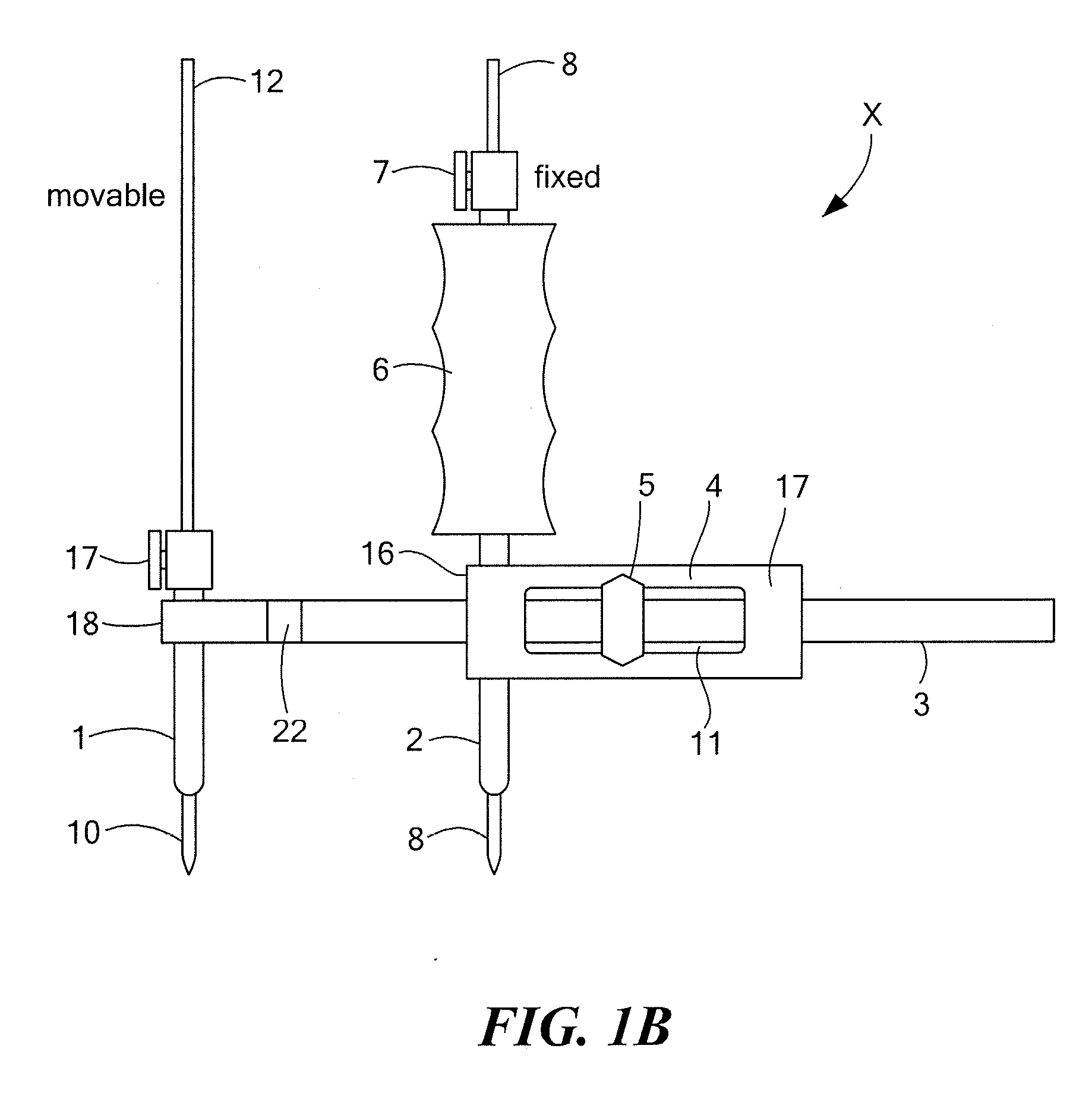
[0038] Referring now to FIG. 1, an isometer X having an elongated cannulated body 4, having a first end 16 and a second end 17, that encases a slider rod 3 with a pointer 5, further having a fixed stylus 2 and corresponding guide pin 8, and a movable stylus 1 and corresponding guide pin 10, is designed for use in determining lateral isometry for restoring rotary and anterior and / or posterior knee stability in combination with ACL and / or PCL reconstruction.

[0039] The slider rod 3 has a first end 18 and second end 19 and a longitudinal slot 20 (see FIG. 3A for slot 20) running part of the length of the rod, and slides horizontally within the hollow elongated body 4. There is also a hole 21 (see FIG. 3B) in first end 18 wherein the movable-stylus guide pin 10 slides vertically within the cannulated movable stylus 1, and is attached transversely through the first end 18 of the slider rod 3. Encircling the slider rod 3 is a pointer 5 that slides with the slider rod 3 but whose position ...


PUM


Abstract

An isometer for determining isometric graft tunnel placement for lateral side surgical augmentation or reconstruction for anterolateral or posterior lateral rotary knee instability. This graft tunnel placement isometry assessment and measurement device is designed to be used with a graft and an extra-articular technique that restores rotatory, lateral, and anterior/posterior knee stability when used by itself or in combination with intra-articular ACL/PCL reconstruction. The isometer includes an elongated body with a slider rod that slides horizontally within the body and a cannulated fixed stylus attached transversely to the first end of the elongated body. Within that cannulated fixed stylus is a guide pin that slides freely but that can also be fixed using a fixed-stylus set screw. Similarly, a cannulated movable stylus is attached transversely to the first end of the slider rod, and within that cannulated movable stylus is a guide pin that slides freely but that can also be fixed using a movable-stylus set screw. There is a pointer encircling the slider rod that slides with the slider rod, but whose position along the slider rod can also be adjusted manually. The slider rod may also have a rotatable member that allows each end of the slider rod to rotate relative to the other end. The rotatable member obviates slider rod impingement during operation. To determine rotary knee isometry during knee reconstructive surgery, the guide pins are positioned over previously identified lateral reconstruction tunnel sites. The guide pins are then driven into the bone tunnel sites and the knee put through a full range of motion by flexing and extending the knee while the isometer position is maintained and the pointer movement is monitored. If movement of the pointer is unacceptably large, the guide pins are re-set, re-positioned and re-driven into different pre-identified lateral reconstruction tunnel sites, and pointer movement during full range motion is again monitored until movement is acceptably small.

Description

PRIORITY [0001] This application is a continuation in part of utility patent application Ser. No. 11 / 125,808, entitled “A Surgical Device for Anterolateral Reconstruction” filed May 10, 2005, attorney docket 1464 / 156, which claims priority from U.S. provisional patent application, Ser. No.: 60 / 569,987, filed on May 11, 2004 entitled “Surgical Device for Anterolateral Reconstruction”, both of which are incorporated by reference herein in their entirety.BACKGROUND OF THE INVENTION [0002] The present invention relates to surgical devices and procedures used in the field of knee surgery, particularly anterolateral and posterolateral reconstruction in combination with reconstruction of the anterior cruciate ligament (ACL) and posterior cruciate ligament (PCL) of the knee. [0003] Three situations have been identified that frequently lead to severe anterolateral and / or posterolateral rotary instability in the knee. In such cases, reconstruction should be considered in combination with ACL ...

Claims


Application Information

Patent Timeline
IPC IPC(8): A61F5/01A61B17/17A61B17/58
CPCA61B17/1764A61B17/1714A61B2090/061
Inventor MCGUIRE, DAVID A.WOLCHOK, JEFFREY C.HENDRICKS, STEVEN D.
Owner MCGUIRE DAVID A
Why Eureka
Try Eureka