
Method for operating a calendar machine for plastic melts

a technology of plastic melt and calendar machine, which is applied in the direction of presses, rotary presses, manufacturing tools, etc., can solve the problems of impact on the roller conveyor and material wear rate, and achieve the effect of reducing production or starting speed, reducing production costs, and maintaining product quality

Inactive Publication Date: 2007-10-18
BREYER MASCHFAB
View PDF2 Cites 2 Cited by
  • Summary
  • Abstract
  • Description
  • Claims
  • Application Information

AI Technical Summary

Benefits of technology

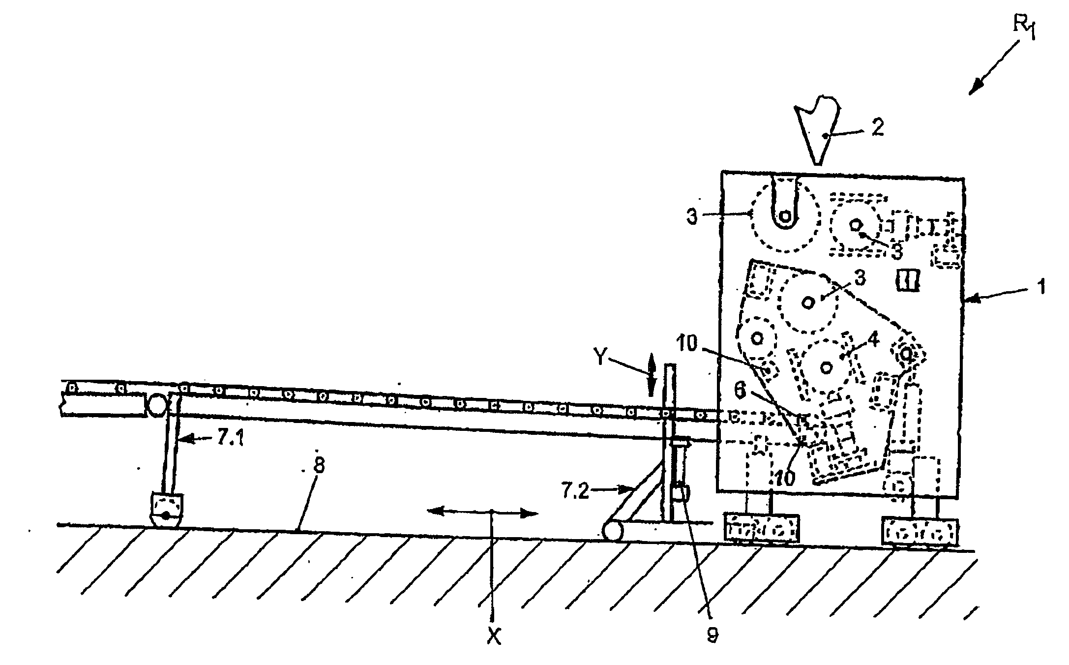
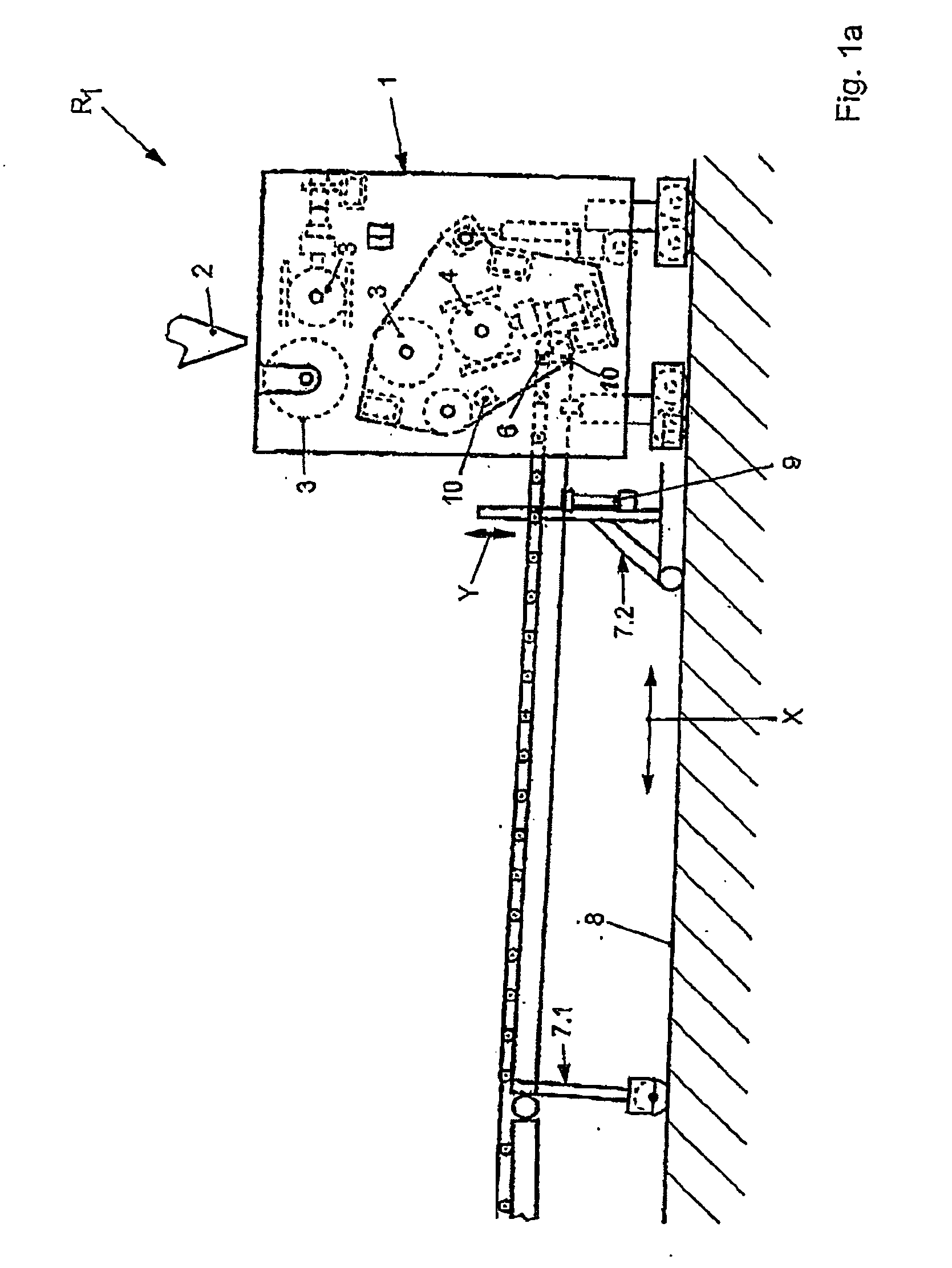
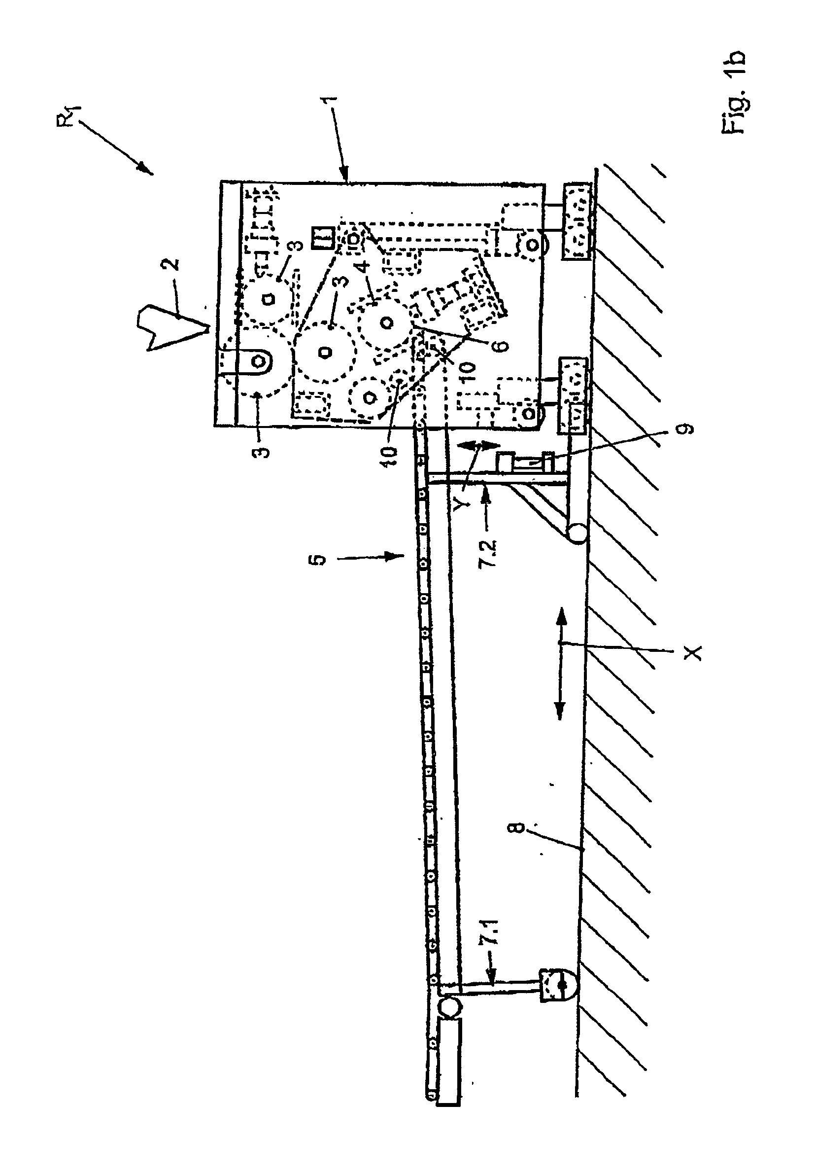
[0011] In the case of the present invention, it has proven to be particularly advantageous for a roller conveyor opposite a last roll of any smoothing calender to run in a controlled and actuable manner in an x- and / or y-direction during operation in order to permanently align a position of the first roll in a roller conveyor with respect to a last roll of the smoothing calender, to accommodate a separation distance, to justify a separation distance and finely adjust a separation distance. This can be advantageous for different processes in the course of operation, i.e. for the starting-up process, for the process of positioning the rolls of the smoothing calender and also for the production process.
[0016] It has, therefore, proven to be specially advantageous that, in particular, the task of starting up a production process in which a plastic melt fed from an extruder or through a broad-slit nozzle and led both to and through the smoothing calender is made less difficult. In that respect, when the processed plastic melt is fed out from the last roll of the smoothing calender, a transfer onto a first roll of a roller conveyor is made much less difficult, since the release point of the completed plate to the first roll of the roller conveyor can be adjusted precisely by positioning the roller conveyor. Manual intervention is no longer necessary; a start-up process can take place automatically.
[0017] Furthermore, it is then possible in the start-up process and particularly in the positioning process for the smoothing calender to set a correspondingly required desired thickness of the plastic plate and also continuously during operation to carry the first roll of the roller conveyor in the method described above towards the last roll of the smoothing calender, which also moves. In this way, higher speeds of production or of starting-up can be undertaken while maintaining the quality of the product.
[0018] In addition, it is guaranteed that in a crash, relative to a background, the roller conveyor can be very quickly lowered at a very high speed so that no melt impacts with the roller conveyor or damages the rolls of the smoothing calender.
[0019] A greater opening speed of the roller conveyor relative to the smoothing calender and, in particular, the last roll of the smoothing calender makes it possible, even in an “emergency stop” situation to effect a rapid shutdown without resulting damage.

Problems solved by technology

Hence, it is disadvantageous that it is not possible to set a release point for the completed plate from the last roll of the smoothing calender to the first roll of the roller conveyor and as a result of this it is often necessary during operation to allow for delays, a higher wear rate of material and manual intervention to ensure that the product which leaves the last roll of the smoothing calender transfers to the roller conveyor.
It is also disadvantageous that, particularly in the event of a crash, the melt impacts upon the roller conveyor, which is equally undesirable.

Method used


Image

  • Method for operating a calendar machine for plastic melts
  • Method for operating a calendar machine for plastic melts
  • Method for operating a calendar machine for plastic melts

Examples


Embodiment Construction

[0028] According to FIG. 1a, a device R1 according to the invention comprises a smoothing calender 1 into which a broad-slit nozzle 2 supplies an extruded plastic melt between the individual rolls 3 of the smoothing calender 1, which bring it to a desired thickness while simultaneously cooling it over the rolls 3 and the last roll 4. Having arrived at the last roll 4 of the smoothing calender 1, the completed plastic plate, film or the like then passes to a roller conveyor 5 or, as can be seen from the FIGS. 1b and 1c, is transferred from the last roll 4 of the smoothing calender 1 to a first roll 6 of the roller conveyor 5 in order then for the manufactured products, for example to be completely cooled on the roller conveyor 5, to be homogenized and then to pass on to a further processing stage such as, for example, a lengthening device, a wind-up device or the like.

[0029] In the case of the present invention, the smoothing calender 1 can be constructed as illustrated as a four-ro...


PUM

PropertyMeasurementUnit
Distanceaaaaaaaaaa

Abstract

A method and a device for operating a calendar machine for plastic melts, the machine comprising a downstream roll conveyor, the position of the roll conveyor being oriented in relation to a position of a roll of the calendar machine.

Description

BACKGROUND OF THE INVENTION [0001] The present invention relates to a process for operating a smoothing calender for plastic melts with a succeeding roller conveyor together with a device for carrying out the process. [0002] In the case of conventional processes, a roller conveyor is positioned securely below the conventional smoothing calender when processing plastic melts to carry away completed plates of plastic or the like, this conveyor being opposite a last roll of a smoothing calender and securely aligned with it. [0003] Hence, it is disadvantageous that it is not possible to set a release point for the completed plate from the last roll of the smoothing calender to the first roll of the roller conveyor and as a result of this it is often necessary during operation to allow for delays, a higher wear rate of material and manual intervention to ensure that the product which leaves the last roll of the smoothing calender transfers to the roller conveyor.[0004] It is also disadva...

Claims


Application Information

Patent Timeline
IPC IPC(8): B30B3/04B29C43/24B29C48/03B29C48/08B29C48/35B29C59/04
CPCB29C43/245B29C47/884B29C47/0009B29C48/03B29C48/08B29C48/9135B29C48/914B29C48/9145B29C48/906
Inventor LUCAS, BERNHARD
Owner BREYER MASCHFAB
Learn More