Protective sleeve assembly having an integral closure member and methods of manufacture and use thereof

a technology of protective sleeves and integral closures, which is applied in the field of sleeves, can solve the problems of increasing the time required, affecting the safety of workers, and affecting the safety of workers, and achieves the effects of convenient removal, convenient securization, and economical manufacture and us

Inactive Publication Date: 2007-10-18
FEDERAL MOGUL WORLD WIDE
View PDF29 Cites 46 Cited by
  • Summary
  • Abstract
  • Description
  • Claims
  • Application Information

AI Technical Summary

Benefits of technology

[0008] A unitized tubular sleeve assembly provides protection to elongate members contained within a sleeve of the assembly. The assembly has material formed into a tubular wall defining an inner surface of the sleeve and an enclosed tubular cavity extending axially along a longitudinal axis between opposite ends of the sleeve. The assembly includes at least one closure member laid-in with the tubular wall material, and as a result of being laid-in, at least a portion of the closure member can move circumferentially relative to the tubular wall. As such, by pulling on the closure member, at least a portion of the wall inner surface is constricted radially toward the longitudinal axis for secure engagement with the elongate member. Conversely, by pulling the sleeve wall radially outwardly, the sleeve wall can be expanded radially outwardly from the longitudinal axis to allow relative axial movement between the sleeve assembly and the elongate member.
[0009] Accordingly, the sleeve assembly can be readily secured to any elongate members contained within the cavity by pulling a portion of the closure member radially outwardly under tension from the sleeve. Thereafter, the sleeve assembly can be selectively released from the elongate members for relative movement therewith by releasing the closure member from tension and pulling radially outwardly on the wall of the sleeve. As such, the sleeve assembly is able to be easily secured to elongate members without the need of additional secondary securing members, such as clamps or tapes, or tools, and is also easily removable from the elongate members without the need of tools. In addition, the sleeve assembly is economical in manufacture and well as in use, while also being aesthetically pleasing and having a long and useful life.
[0010] Another aspect of the invention provides a unitized heat resistant tubular sleeve assembly that provides a thermal barrier to elongate members contained within a sleeve of the assembly. The assembly has heat resistant material knitted into a tubular wall defining an inner surface of the sleeve and an enclosed tubular cavity extending axially along a longitudinal axis between opposite ends of the sleeve. The assembly includes at least one heat resistant closure member laid-in with the tubular wall material, and as a result of being laid-in, at least a portion of the closure member can move circumferentially relative to the tubular wall. As such, by pulling on the closure member to extend it outwardly from the wall, at least a portion of the wall inner surface constricts radially toward the longitudinal axis for secure engagement with the elongate member. Conversely, by pulling the sleeve wall radially outwardly, the sleeve wall can be expanded radially outwardly from the longitudinal axis to allow relative axial movement between the sleeve assembly and the elongate member.
[0014] Sleeve assemblies constructed in accordance with one aspect of the invention are useful for shielding heat radiation from entering and / or exiting the tubular cavity of the sleeve assembly. The sleeve assemblies can be made to accommodate virtually any package size and shape by adjusting their cavity diameter, their flexibility, and their length in manufacture, and can be equipped with a variety of types and numbers of closure members in accordance with the invention. The sleeve assemblies are readily securable to an elongate member to prevent relative axial movement of the sleeve along the elongate member. The sleeve assemblies are also readily removable from the elongate member without the need of secondary tools. In addition, sleeve assemblies constructed in accordance with the invention are relatively economical in manufacture and in use, and exhibit a long and useful life.

Problems solved by technology

Unfortunately, clamps often require a separate tool, such as a screwdriver, to be used to secure the clamp about the sleeve in assembly, and to remove the clamp in service.
In addition, clamps can increase the time required to secure the sleeving to the elongate members, they can be unsightly, they can get hot, they can cause damage to adjacent components, and they can also prove costly.
Unfortunately, as with clamps, using tape can increase the time required to secure the sleeving in place, and it can prove cumbersome and difficult to apply, particularly in tight spaces.
Also, utilizing tape requires making sure an adequate supply of tape is on hand at all times, and it can also make servicing the elongate items difficult, in that the tape may be difficult to remove once applied.
Further, removal of the tape may cause damage to the underlying sleeving, thereby adding further cost associated with the repair or replacement of the damaged sleeving.
In addition, tapes can be unsightly, which could be a concern in areas having high visibility.
Thus, although clamps, tapes, and other secondary mechanisms used to secure protective sleeving to elongate members can prove effective in preventing relative movement between the sleeving and the elongate members, they typically come with negative consequences.

Method used


Image

  • Protective sleeve assembly having an integral closure member and methods of manufacture and use thereof
  • Protective sleeve assembly having an integral closure member and methods of manufacture and use thereof
  • Protective sleeve assembly having an integral closure member and methods of manufacture and use thereof

Examples


Embodiment Construction

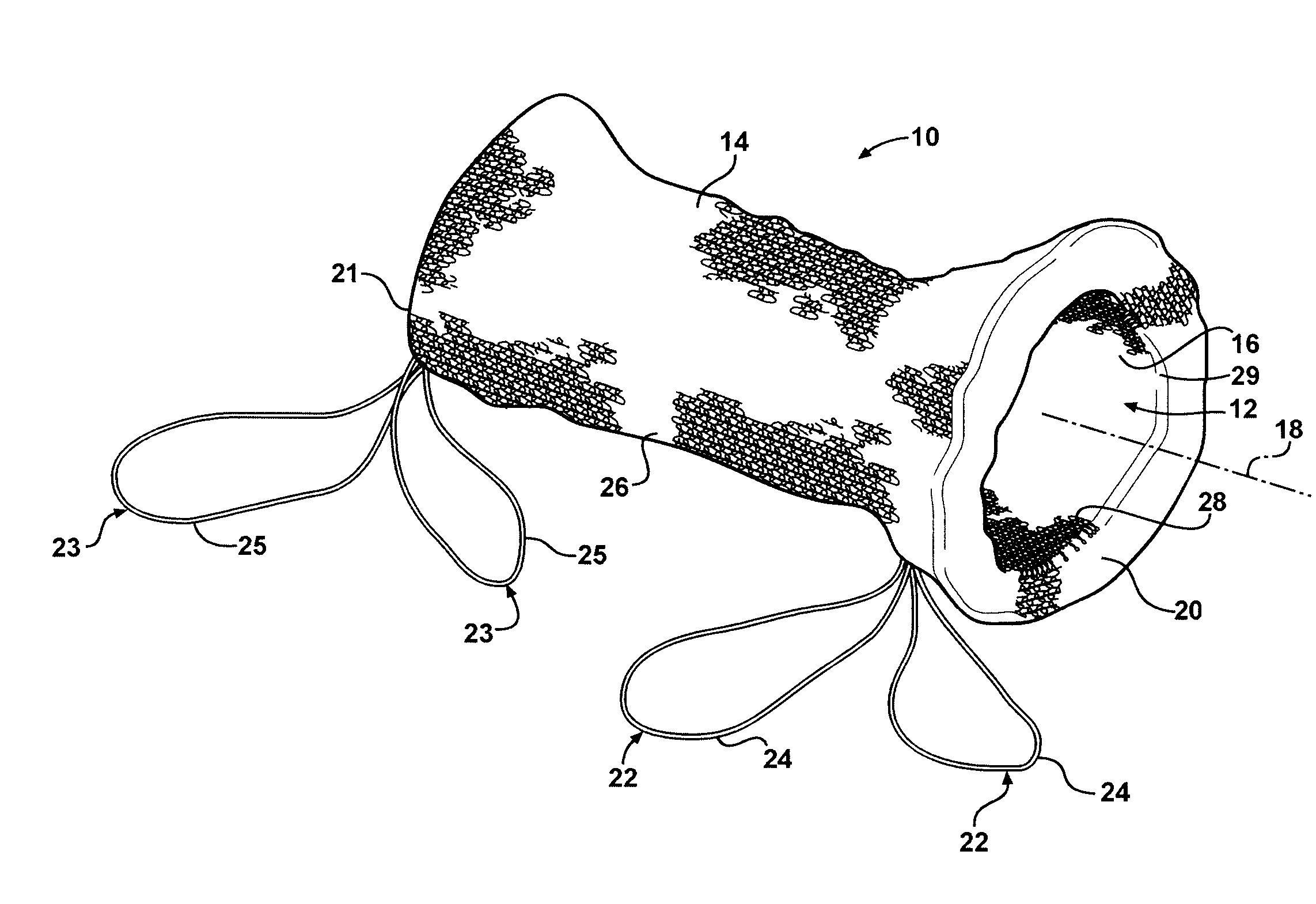
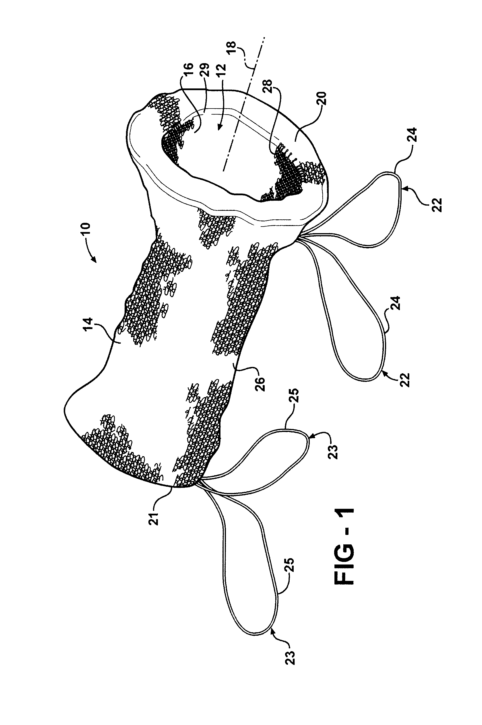
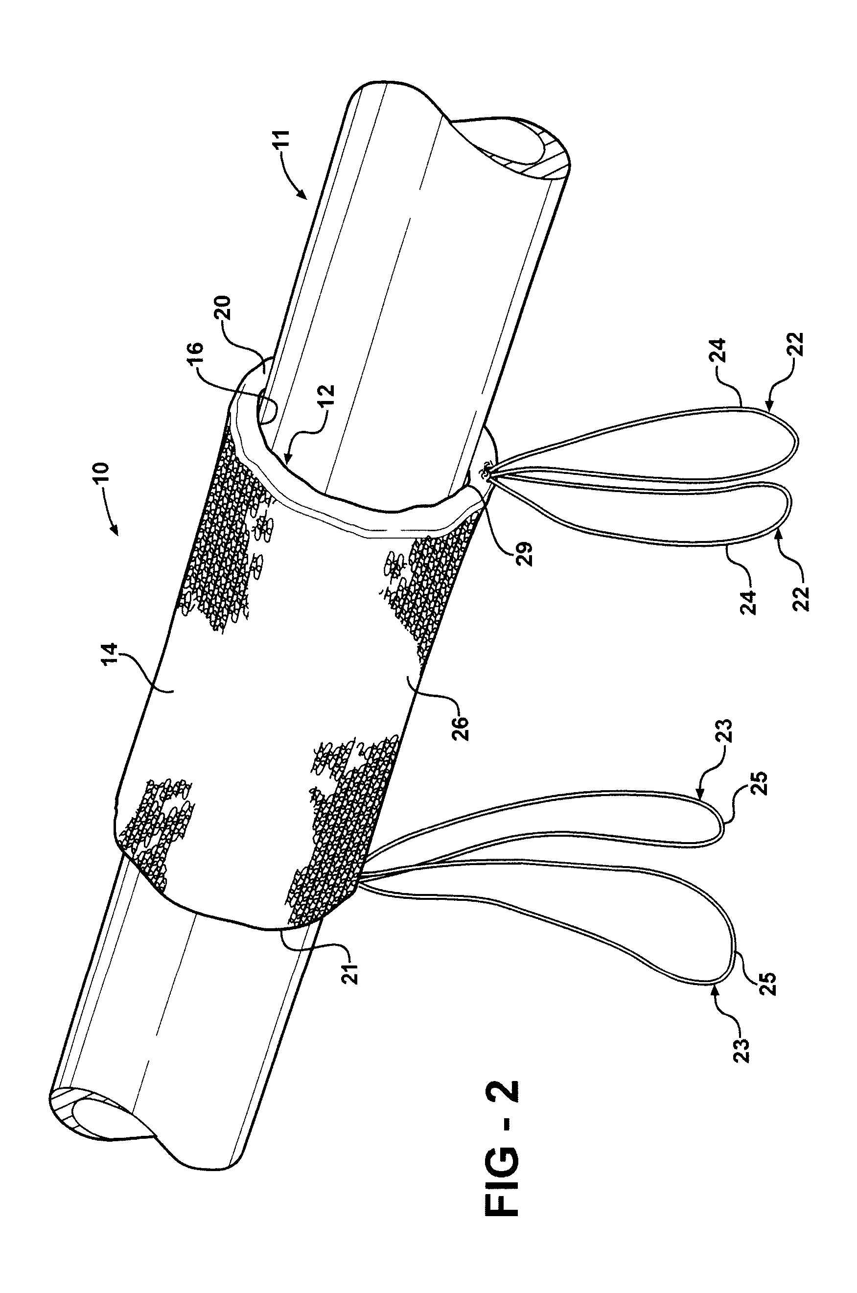
[0021] Referring in more detail to the drawings, FIGS. 1-6 show a tubular sleeve assembly 10 constructed according to one presently preferred embodiment of the invention. The sleeve assembly provides protection to one or more elongate members 11 (FIG. 2) received within an enclosed tubular cavity 12 of the assembly 10. The assembly 10 has a plurality of yarns knitted into a tubular walled sleeve 14 having an inner surface 16 defining the cavity 12 extending axially along a longitudinal axis 18 between opposite ends 20, 21 of the sleeve 14. The sleeve assembly 10 has at least one elongate closure member, and represented here, for example, as a pair of elongate closure members 22, 23 integrally constructed with the sleeve 14 to provide the sleeve assembly 10 as a unitized, one-piece structure. At least a portion of the closure members 22, 23 can be pulled outwardly, represented here as respective loop portions 24, 25, for example, thereby causing the outwardly extending loop portion 2...


PUM


Abstract

A protective sleeve assembly for elongate members has a tubular wall with an inner surface providing a cavity extending along a longitudinal axis between opposite ends of the sleeve. The assembly includes at least one closure member laid-in with the tubular wall, such that at least a portion of the closure member within the tubular wall is moveable relative to the tubular wall. At least a portion of the wall inner surface is constricted toward the longitudinal axis to engage the elongate member upon pulling the closure member outwardly from the wall. The sleeve is expandable radially outwardly from the longitudinal axis to allow relative axial movement between the sleeve assembly and the elongate member by pulling the sleeve wall radially outwardly.

Description

CROSS-REFERENCE TO RELATED APPLICATION [0001] This application claims the benefit of U.S. Provisional Application Ser. No. 60 / 792,522, filed Apr. 17, 2006, which is incorporated herein by reference in its entirety.BACKGROUND OF THE INVENTION [0002] 1. Technical Field [0003] This invention relates generally to sleeves for protecting elongate members and more particularly to tubular protection sleeves having a closure mechanism for maintaining the sleeves against relative axial movement along the elongate members. [0004] 2. Related Art [0005] Tubular sleeves are known for use to protect and provide a barrier to heat radiation to elongate members, such as wires and tubing, contained within the sleeves. The sleeves are commonly constructed from abrasion resistant and / or heat resistant and / or fire retardant yarns to withstand relatively high temperatures. Sometimes the sleeves are used to insulate high temperature tubes, such as those providing a conduit for hot liquid, to inhibit the he...

Claims


Application Information

Patent Timeline
Patent Type & Authority Applications(United States)
IPC IPC(8): H02G15/08
CPCH02G3/0481H02G3/0412F16L59/021F16L57/04F16L59/145D04B1/123D10B2505/12
Inventor OTT, DONALD C. JR.HARRIS, DAVID ANDREWLUDY, LINWOODMALLOY, CASSIE M.
Owner FEDERAL MOGUL WORLD WIDE
Why Eureka
Try Eureka