Intravenous needle assembly and method of use

a technology of intravenous needles and needles, which is applied in the direction of intravenous devices, catheters, infusion needles, etc., can solve the problems of needle rupture or detachment from the vein, difficulty in maintaining the needle position in the patient's vein during use, and difficulty even for experienced care providers to perform procedures

Inactive Publication Date: 2007-10-18
ABBOTT JOSHUA L
View PDF14 Cites 2 Cited by
  • Summary
  • Abstract
  • Description
  • Claims
  • Application Information

AI Technical Summary

Benefits of technology

[0008] The present invention achieves its objectives by providing an intravenous needle assembly that includes a needle with a central axis, a hollow interior extending along the central axis, and opposed first and second ends. A body having a top in opposed relation to a bottom is secured to the needle. A fluid conduit interconnects the second end of the needle with an attachment mechanism. A compressible member is attached to the needle assembly for being placed in a compressed state to obtain a desired position of the needle during use. A fastener is used to secure the needle assembly to the patient while the compressible member is in a compressed state so that compression of the compressible member is maintained during use.

Problems solved by technology

One of the shortcomings of prior art butterfly needles is the difficulty associated with maintaining the needle at a proper position in the patient's vein during use.
Even a small amount of needle movement can place unwanted stress on the vein and cause the needle to rupture the vein or to detach from the vein.
When using a butterfly needle to collect blood, the care provider must hold the needle in place with one hand while collecting blood samples with the other hand—a difficult procedure even for experienced care providers.
Unfortunately, intravenous needles available today do not effectively or efficiently maintain proper needle positioning.
Instead, the position of the needle during use is dependent on the inconsistent ability of the care provider to hold the needle in place.

Method used


Image

  • Intravenous needle assembly and method of use
  • Intravenous needle assembly and method of use
  • Intravenous needle assembly and method of use

Examples


Embodiment Construction

[0015] It is to be understood that the invention that is now to be described is not limited in its application to the details of the construction and arrangement of the parts illustrated in the accompanying drawings. The invention is capable of other embodiments and of being practiced or carried out in a variety of ways. The phraseology and terminology employed herein are for purposes of description and not limitation.

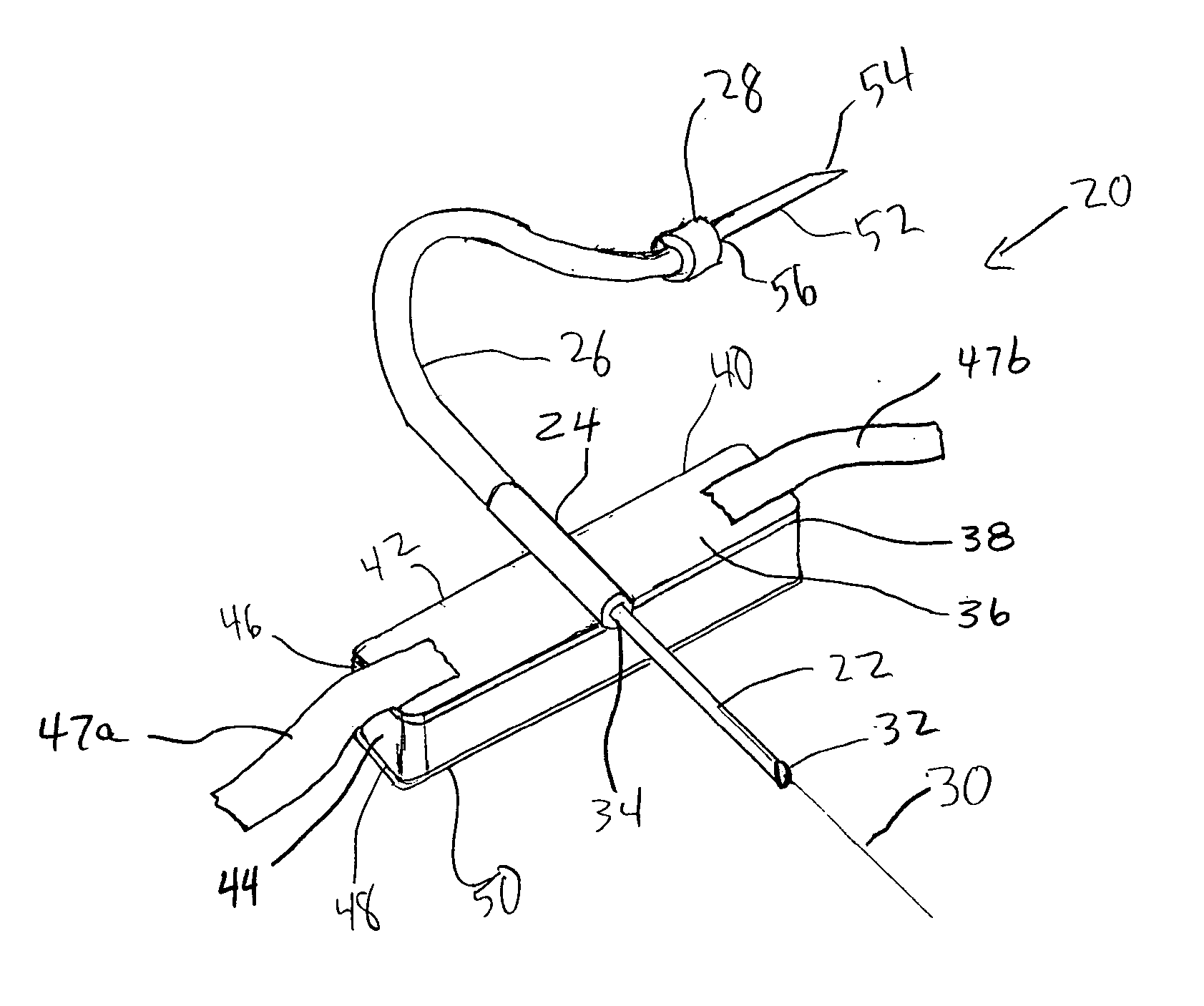
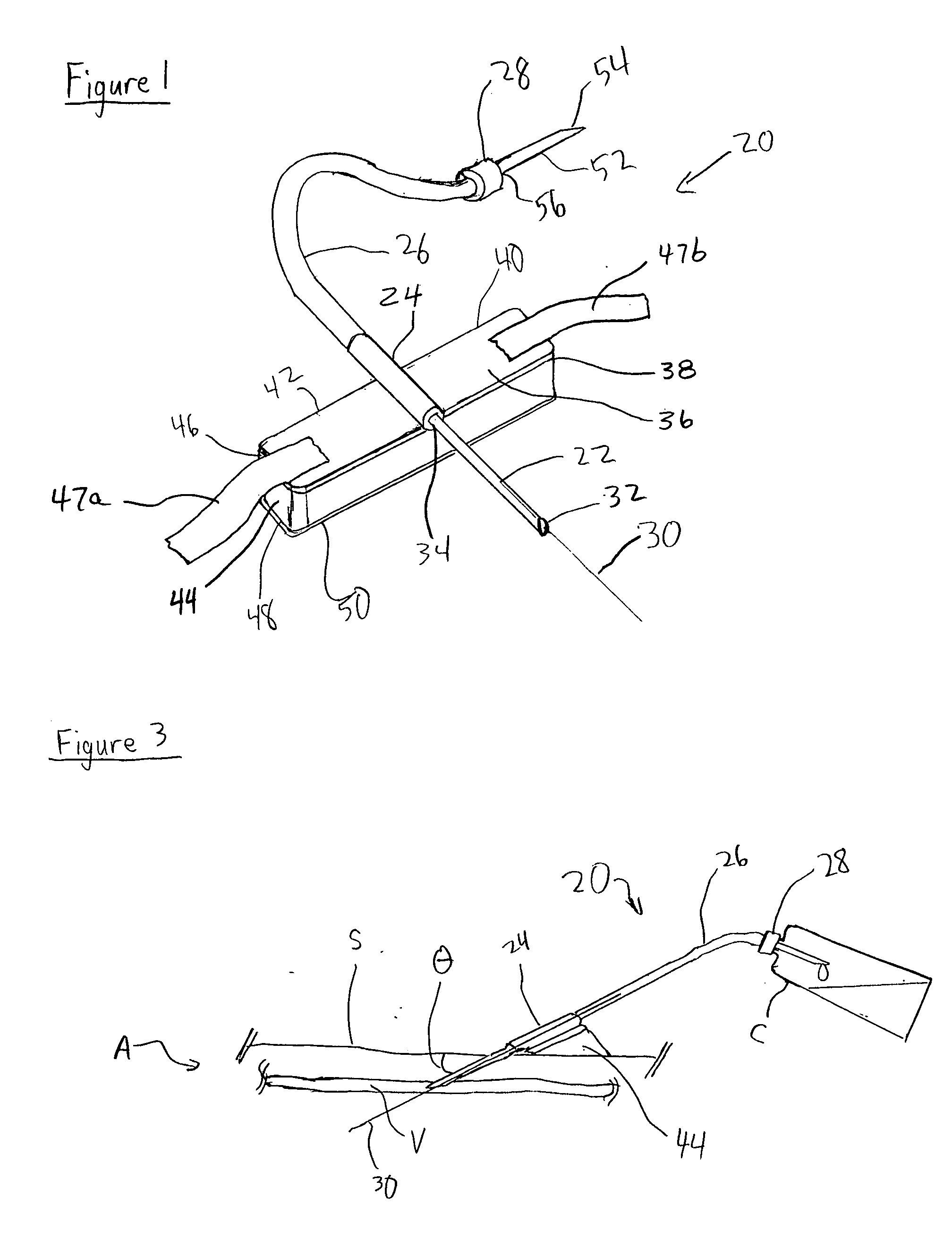
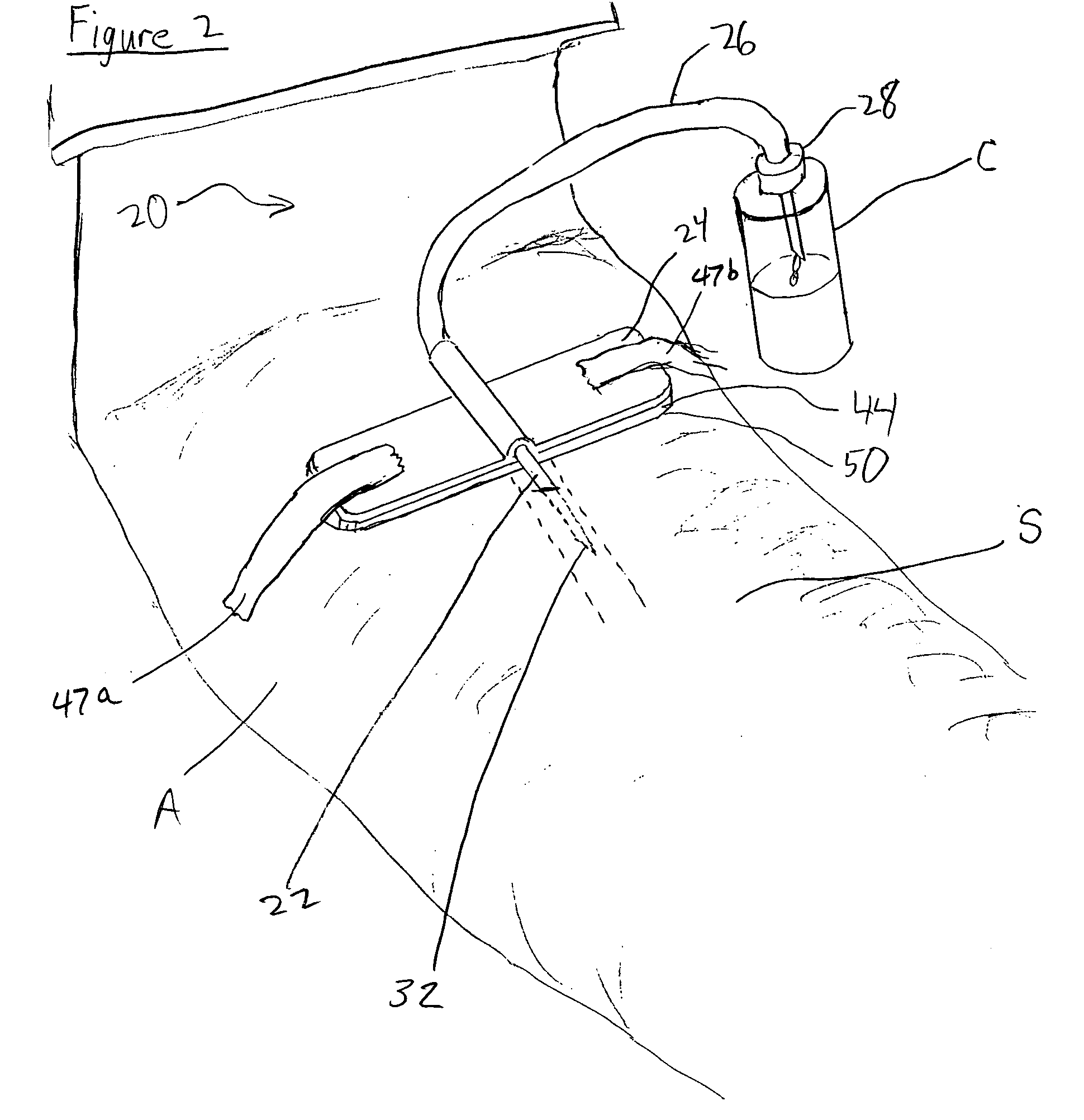
[0016] Turning now to FIG. 1, an intravenous needle assembly 20 according to the present invention includes an intravenous needle 22, a body 24, a fluid conduit 26 and an attachment mechanism 28. The intravenous needle 22 preferably has a generally cylindrical shape with a central axis 30, a first end 32 and a second end 34 in opposed relation to the first end 32. The intravenous needle 22 has a hollow interior extending along the central axis 30.

[0017] The body 24 is secured to the needle 22 and includes a top 36 in opposed relation to a bottom 38. The general shape...


PUM


Abstract

An intravenous needle assembly includes a compressible member for uses such as drawing blood and infusing intravenous fluids or medication. The intravenous needle assembly also includes an intravenous needle, a body to which the compressible member is attached, a fastener for maintaining a desired position of the needle during use, an attachment mechanism and a fluid conduit in fluid communication with the intravenous needle and attachment mechanism. In use, the needle is inserted into a patient's vein. The compressible member is compressed to position the needle as desired, and the fastener is employed to secure the needle assembly to the patient in a way that maintains compression on the compressible member. The needle assembly may be further secured to the patient by an adhesive disposed on the bottom surface of the compressible member. The attachment mechanism may be attached to a container for blood collection.

Description

REFERENCE TO PENDING APPLICATIONS [0001] This application is not based upon any pending domestic or international patent applications. REFERENCE TO MICROFICHE APPENDIX [0002] This application is not referenced in any microfiche appendix. FIELD OF THE INVENTION [0003] The present invention generally relates to intravenous needles. More specifically, the present invention relates to an intravenous needle uniquely configured to maintain the needle at a desired position during use. BACKGROUND OF THE INVENTION [0004] There are many uses for intravenous needles in the medical industry. Some of the more common uses of intravenous needles include administering medicine, drawing blood samples, and providing patients with intravenous fluids. [0005] Intravenous needles are available in various configurations. So-called “butterfly” needles include wings or tabs that extend out perpendicular to the needle to help secure and steady the needle when the wings are grasped by the care provider. A sma...

Claims


Application Information

Patent Timeline
Patent Type & Authority Applications(United States)
IPC IPC(8): A61M5/32
CPCA61M5/158A61M2025/028A61M2025/0253A61M25/02
Inventor ABBOTT, JOSHUA L.
Owner ABBOTT JOSHUA L
Why Eureka
Try Eureka