Suspension system for electric heavy-duty vehicle

a suspension system and electric heavy-duty technology, applied in the direction of resilient suspensions, vehicle springs, propulsion parts, etc., can solve the problems of battery pack constraints along the underside, affecting the stability of the vehicle, and requiring adjustments to the suspension system, so as to improve the initial acceleration and reduce fossil fuel combustion. , the effect of increasing traction

Active Publication Date: 2022-02-03
DANA HEAVY VEHICLE SYSTEMS GROUP LLC
View PDF7 Cites 2 Cited by
  • Summary
  • Abstract
  • Description
  • Claims
  • Application Information

AI Technical Summary

Benefits of technology

[0002]An internal combustion engine heavy-duty vehicle may be configured with rear-wheel drive to enhance initial acceleration and increase traction. Increasing interest in reducing fossil fuel combustion has led to efforts to provide electric heavy-duty vehicles. In order to electrically propel such vehicles, a large battery pack may be demanded. The battery pack may be positioned low in the vehicle, such as along a chassis of the vehicle, and may have a large footprint, resulting in packaging constraints along an underside of the vehicle. Furthermore, a low vertical positioning of a floor of the vehicle, and hence the chassis and the battery pack, may be desirable in heavy-duty vehicles to enable efficient loading and unloading thereof.
[0004]In one example, the issues described above may be addressed by a system for a vehicle, the system including a wheel hub assembly coupled to a frame of the vehicle via a first wishbone arm and a second wishbone arm, and an air spring coupled at opposite ends to a first link and a second link, each of the first link and the second link being pivotably coupled to the frame of the vehicle, the second link further being pivotably coupled to the first wishbone arm, wherein the air spring may be positioned above the wheel hub assembly with respect to the vehicle. In this way, an air suspension system may be provided for a low-floor heavy-duty vehicle by positioning the air spring so as to not interfere with drive shafts of the wheel hub assembly and to provide increased lowering of a cabin floor of the vehicle.
[0005]In some examples, the vehicle may be provided with air springs above both front wheel hub assemblies and rear wheel hub assemblies, wherein a configuration of the air springs at the front wheel hub assemblies may be different from a configuration of the air springs at the rear wheel hub assemblies. For example, at the front wheel hub assemblies, the second link may be a leveling link, provided to maintain substantially axial compression of the air spring between a maximally expanded position and a maximally compressed position. Further, at the rear wheel hub assemblies, the air springs may be fixedly coupled to a single rear axle, the single rear axle being coupled to rear trailer wheels. In this way, the air spring may not utilize any axially guiding structure extending a length thereof, allowing for ease of manufacture and maintenance by reducing a total number of obstructing or specialized components (e.g., guiding structures, uniquely configured air springs, etc.) at the front and rear wheel hub assemblies. Accordingly, the air suspension system may be adapted to the low-floor heavy-duty vehicle as configured for front-wheel drive.

Problems solved by technology

The battery pack may be positioned low in the vehicle, such as along a chassis of the vehicle, and may have a large footprint, resulting in packaging constraints along an underside of the vehicle.
The large size of the battery pack and low floor of the vehicle may demand modifications to various vehicle components and systems.
The lack of packaging space between the rear wheels may also demand adjustments to a suspension system at the vehicle rear wheels.

Method used


Image

  • Suspension system for electric heavy-duty vehicle
  • Suspension system for electric heavy-duty vehicle
  • Suspension system for electric heavy-duty vehicle

Examples


Embodiment Construction

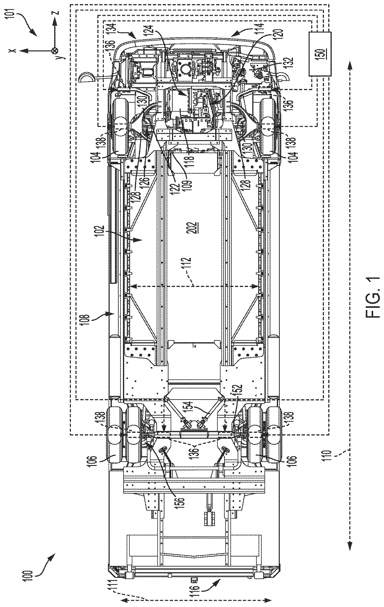
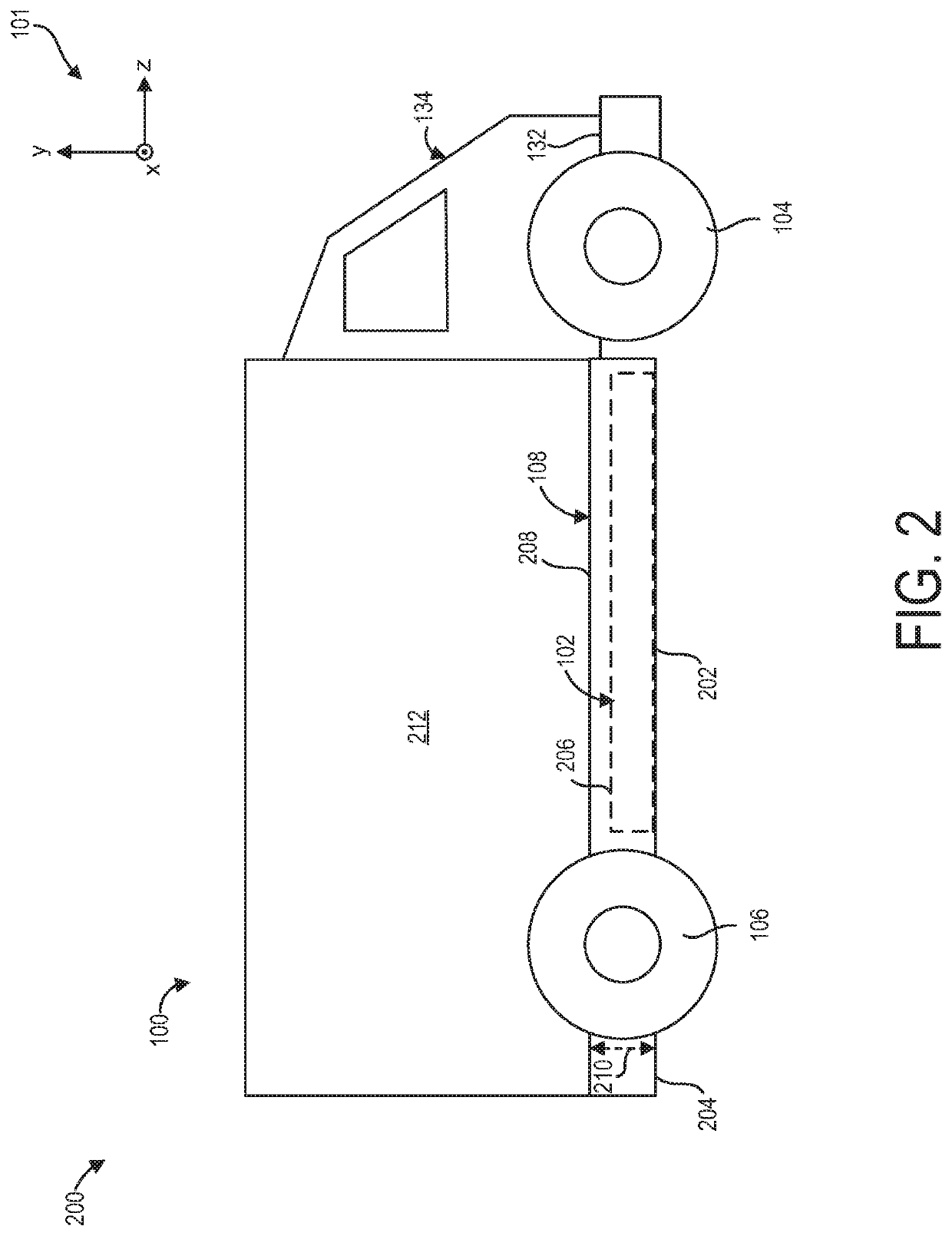
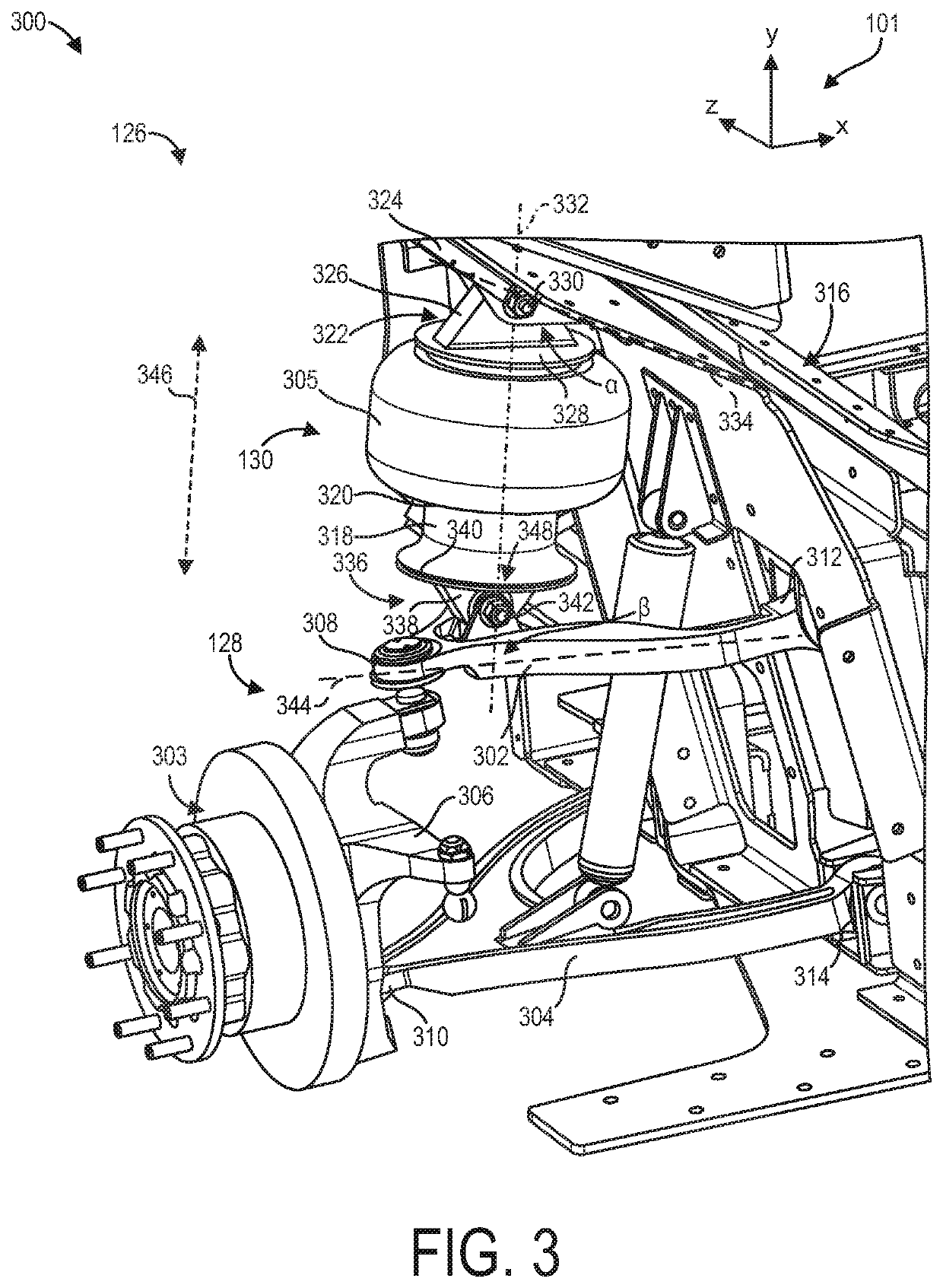
[0017]The following description relates to suspension systems for an electric heavy-duty vehicle. The vehicle may have a low floor to enable low effort loading and unloading of objects onto a body of the vehicle. In some examples, the low floor may be a chassis of the vehicle with an integrated battery pack, as shown in FIGS. 1 and 2. To accommodate such a low positioning of the chassis and the integrated battery pack, the vehicle may be adapted with front-wheel drive. However, implementation of front-wheel drive in the vehicle may demand reconfiguration of a front suspension system of the vehicle. An example of an air suspension system at the front axle is depicted in FIG. 3. The front suspension system may combine a double wishbone suspension with an air spring. The air spring may be configured with a leveling link to accommodate angular changes in the double wishbone suspension without demanding installation of an axial guide. The leveling link may preclude obstructing or special...


PUM


Abstract

Methods and systems are provided for an electric heavy-duty vehicle. In one example, a system for the vehicle may include a wheel hub assembly coupled to a frame of the vehicle via a first wishbone arm and a second wishbone arm, and an air spring coupled at opposite ends to a first link and a second link, each of the first link and the second link being pivotably coupled to the frame of the vehicle, the second link further being pivotably coupled to the first wishbone arm. The air spring may be positioned above the wheel hub assembly with respect to the vehicle.

Description

FIELD[0001]The present description relates generally to suspension systems for an electric heavy-duty vehicle.BACKGROUND AND SUMMARY[0002]An internal combustion engine heavy-duty vehicle may be configured with rear-wheel drive to enhance initial acceleration and increase traction. Increasing interest in reducing fossil fuel combustion has led to efforts to provide electric heavy-duty vehicles. In order to electrically propel such vehicles, a large battery pack may be demanded. The battery pack may be positioned low in the vehicle, such as along a chassis of the vehicle, and may have a large footprint, resulting in packaging constraints along an underside of the vehicle. Furthermore, a low vertical positioning of a floor of the vehicle, and hence the chassis and the battery pack, may be desirable in heavy-duty vehicles to enable efficient loading and unloading thereof.[0003]The large size of the battery pack and low floor of the vehicle may demand modifications to various vehicle com...

Claims


Application Information

Patent Timeline
Patent Type & Authority Applications(United States)
IPC IPC(8): B60G11/27B60G17/052B60G7/02B60G7/00
CPCB60G11/27B60G17/052B60G7/02B60G7/008B60G2202/152B60G2204/126B60G2800/914B60G2204/148B60G2300/026B60G2300/50B60G2400/05162B60G2500/30B60G2204/143B60G11/28B60G3/20B60K1/04B60G2200/144
Inventor DESOURDY, GUILLAUMESOARES, JASON
Owner DANA HEAVY VEHICLE SYSTEMS GROUP LLC
Why Eureka
Try Eureka