Self telescopic sleeve type load bearing rail

A self-telescopic, sleeve-type technology, applied in the direction of lifting device, loading/unloading, transportation and packaging, etc., can solve the problems of low container loading and unloading efficiency, difficulty in meeting modern loading and unloading needs, limited advance and retreat of forklift operation, and achieve simplified automation The loading and unloading process, the convenience of carrying and disassembling, and the effect of improving the quality of work

Active Publication Date: 2016-07-06
朱红蔚
View PDF6 Cites 3 Cited by
  • Summary
  • Abstract
  • Description
  • Claims
  • Application Information

AI Technical Summary

Problems solved by technology

[0003] The traditional mechanized loading and unloading relies on the driver to operate the forklift. There are a series of problems in the traditional loading and unloading work of the forklift: 1. The floor of the container compartment is uneven, which causes the forklift to be bumpy during the loading and unloading process, which is prone to accidents; 2. The loading and unloading platform and There are gaps between the containers, and seamless docking cannot be achieved; 3. The space in the container is limited, and the forklift can move forward and backward in a limited space; 4. The size of the loading and unloading wheels is different, and it is difficult to use a forklift of one specification to complete all the loading and unloading work ;5. Traditional forklift loading and unloading leads to low efficiency of container loading and unloading
This series of problems makes the traditional forklift loading and unloading work more and more difficult to meet the modern loading and unloading needs

Method used


Image

  • Self telescopic sleeve type load bearing rail
  • Self telescopic sleeve type load bearing rail
  • Self telescopic sleeve type load bearing rail

Examples


Embodiment Construction

[0031] Below the present invention will be further described in conjunction with the embodiment in the accompanying drawing:

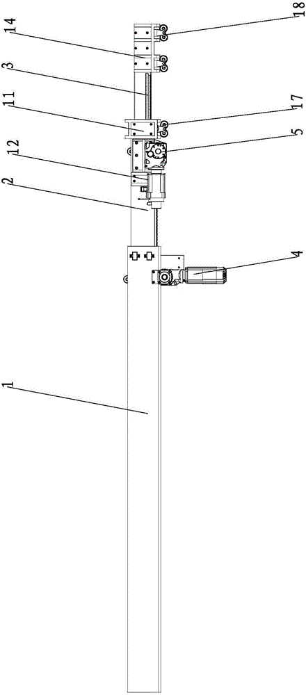
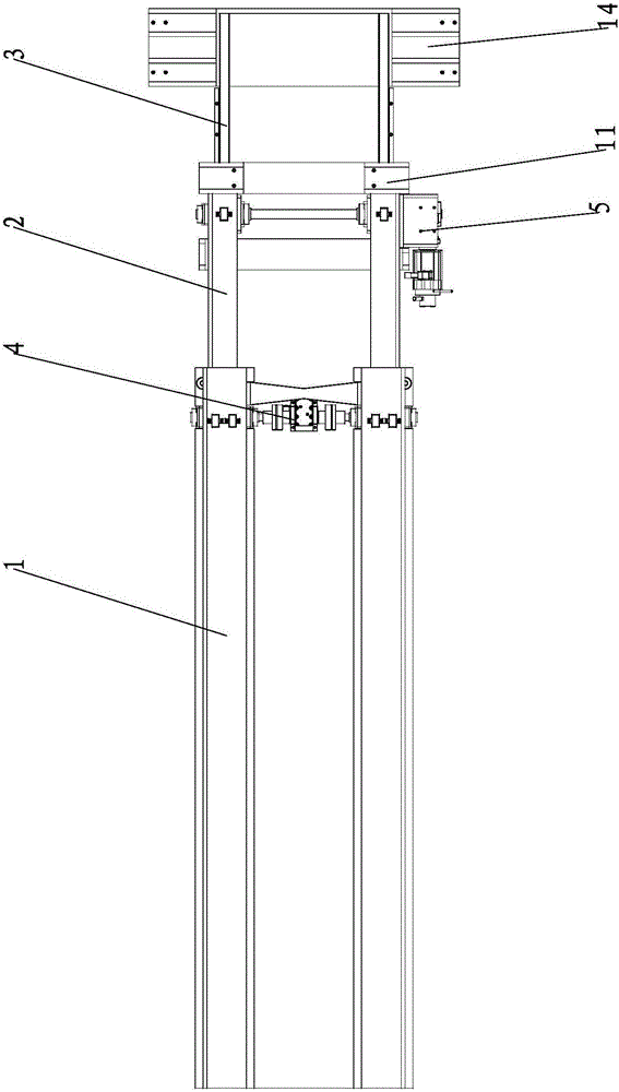
[0032] Such as Figure 1~3 As shown, the present invention mainly includes a primary track assembly 1 , a secondary track assembly 2 , a tertiary track assembly 3 , a secondary track drive component 4 and a tertiary track drive component 5 .

[0033] The primary track assembly 1 includes two primary tracks 6, and the two primary tracks 6 are symmetrically arranged left and right. One end of the two primary rails 6 is connected into one body through a secondary rail drive assembly mounting frame 7, and the secondary rail drive assembly mounting frame 7 is provided with a secondary rail drive assembly 4.

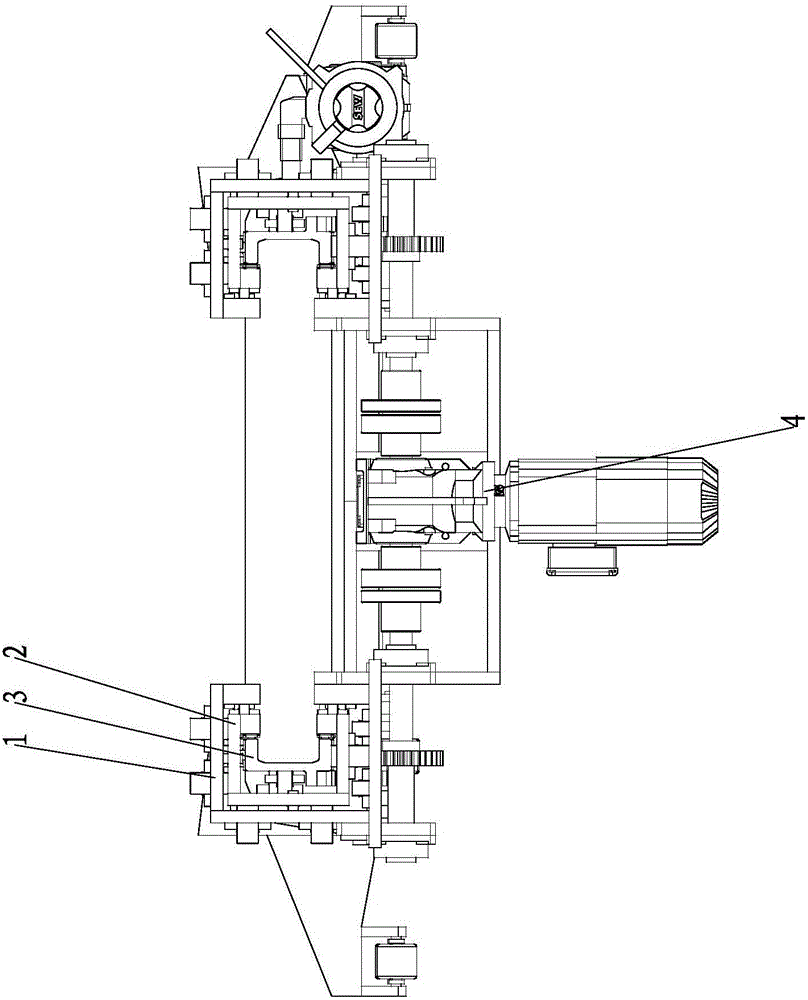
[0034] Such as Figure 4 As shown, the first-level track 6 includes a first-level track vertical plate 6.1, a first-level track upper plate 6.2, a first-level track lower plate 6.3, a first-level track upper load-bearing plate 6.4 and a first-level t...


PUM


Abstract

The invention relates to a load bearing rail, in particular to a self telescopic sleeve type load bearing rail, and belongs to the technical field of robot rail equipment. The self telescopic sleeve type load bearing rail comprises a primary rail assembly, a secondary rail assembly, a tertiary rail assembly, a secondary rail driving assembly and a tertiary rail driving assembly, wherein the secondary rail driving assembly is arranged on a secondary rail driving assembly installing frame; the inner side of the primary rail assembly is glidingly connected with the secondary rail assembly; the tertiary rail driving assembly is arranged between two secondary rails; the inner side of the secondary rail assembly is glidingly connected with the tertiary rail assembly. The self telescopic sleeve type load bearing rail is a load bearing rail for an automatic loading and unloading system; the engagement between a loading and unloading platform and a container is completed; the free shuttling of a forklift in the rail is realized, so that the container lorry loading and unloading automation is realized; the rail is applied to the field of automatic loading and unloading, and completely overturns the original AGC (automatic gain control) loading and unloading mode; the loading and unloading coordinate control is realized, so that the vehicle loading and unloading becomes simple, efficient and energy-saving.

Description

technical field [0001] The invention relates to a load-bearing track, in particular to a self-expandable sleeve-type load-bearing track, which belongs to the technical field of robot track equipment. Background technique [0002] In the existing technology, the proportion of container transportation in the logistics field is increasing, but at this stage, the loading and unloading of most of the goods in the container still relies on manpower, especially the loading and unloading of plastic particles, grain, cement and other bagged goods is completely manual loading and unloading . With the gradual increase of labor costs and the reduction of manual laborers, the loading and unloading of container cargo has become the primary problem faced by logistics companies. Therefore, it has become an urgent problem for logistics companies to find a way to realize the mechanized loading and unloading of trucks. [0003] The traditional mechanized loading and unloading relies on the dr...

Claims


Application Information

Patent Timeline
Patent Type & Authority Applications(China)
IPC IPC(8): B65G67/02B66F9/06
CPCB65G67/02B66F9/06
Inventor 王世鑫崔少中熊壮
Owner 朱红蔚
Why Eureka
Try Eureka