System and method for translating between a global view of a system process and a set of interacting processes

Inactive Publication Date: 2007-10-18
IBM CORP
View PDF14 Cites 0 Cited by
  • Summary
  • Abstract
  • Description
  • Claims
  • Application Information

AI Technical Summary

Problems solved by technology

However, process flow graphs do not explicitly identify the participant of the transaction that is performing a particular action.

Method used


Image

  • System and method for translating between a global view of a system process and a set of interacting processes
  • System and method for translating between a global view of a system process and a set of interacting processes
  • System and method for translating between a global view of a system process and a set of interacting processes

Examples


Embodiment Construction

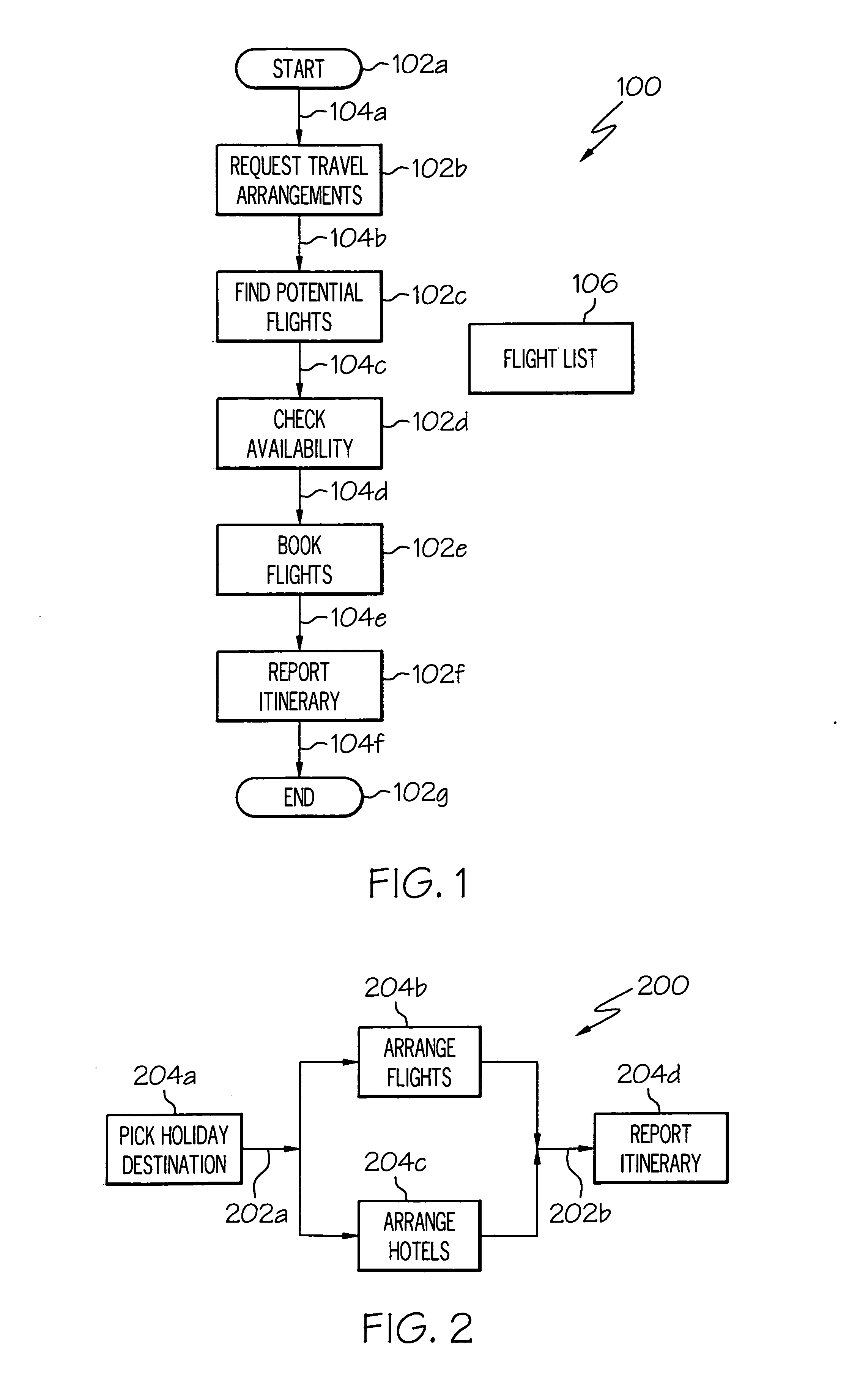
[0017] Referring now to the figures, and in particular, referring now to FIG. 1 there is illustrated a process flow graph 100, which depicts a process flow graph for purchasing airline tickets. A “process flow graph” is a model of a real-world or computer-implemented transaction that includes a pattern of behavior described as a network of “actions” (e.g., actions 102a-g) and “flows” (e.g., flows 104a-f). Process flow graph 100 represents a “global view” of the process, which describes an interaction or transaction as a single connected process even though different participants or roles may ultimately perform the various actions. An “action” designates some individual behavior performed by one participant or role in a process flow graph. Each action has one or more input points and one or more output points. The action includes a description of a particular behavior that the action represents.

[0018] A “flow” represents a dependency between two actions. A “process” describes the wa...


PUM


Abstract

A method, apparatus, and computer-usable medium for graphically depicting a behavior as a global process flow graph, wherein the global process flow graph includes a collection of actions performed by at least two roles; and transforming the global process flow graph into a collection of local processes, wherein each local process includes all actions performed by exactly one role among the at least two roles.

Description

BACKGROUND OF THE INVENTION [0001] 1. Technical Field [0002] The present invention relates in general to the field of computers and similar technologies, and in particular, to software utilized in this field. [0003] 2. Description of the Related Art [0004] A “process flow graph” models real-world or computer-implemented transactions as a collection of actions and flows. However, process flow graphs do not explicitly identify the participant of the transaction that is performing a particular action. Therefore, a transaction may be modeled as a collection of partitioned transactions, where each partitioned transaction explicitly identifies the participant that is performing the partitioned transaction. There is a need for a system and method for transforming a process flow graph to a collection of partitioned transactions. SUMMARY OF THE INVENTION [0005] The present invention includes a method, apparatus, and computer-usable medium for graphically depicting a behavior as a global proc...

Claims


Application Information

Patent Timeline
IPC IPC(8): G06F17/00
CPCG06F8/60G06F8/10
Inventor NALLY, MARTIN P.RUMBAUGH, JAMES E.
Owner IBM CORP
Why Eureka
Try Eureka