Support table assembly for food product breading machine

a technology for breading machines and support tables, which is applied in the direction of revolving cabinets, furniture parts, food shaping, etc., can solve the problems of affecting the breading machine's breading machine's breading machine, and requiring a large amount of space, so as to facilitate the sliding of the breading assembly

Inactive Publication Date: 2007-10-25
BETTCHER INDUSTRIES
View PDF22 Cites 2 Cited by
  • Summary
  • Abstract
  • Description
  • Claims
  • Application Information

AI Technical Summary

Problems solved by technology

The support table poses a number of difficulties.
In breading machines used in restaurants, space is typically very limited and the breading machine will be placed with the second or back end against a wall.
Utilizing the lug carts is also problematic.
The lug carts are often top heavy and pose a tipping hazard.
Because the carts are wheeled, they also tend to move easily when bumped or jostled or simply from vibration of the breading machine.
If the cart moves, finished product can miss the lug and fall onto the floor, thereby increasing waste and posing a slipping hazard.
Further, when a lug is full, an employee has to bend over and remove the lug from the cart.
This exposes the employee to back strain from lifting a heavy lug from the low height of the cart.
Finally, lug carts do not provide a surface surrounding the lugs to direct material into the lug.
This is especially problematic with respect to cleaning out the breading from the breading machine.
Because the support table is generally wider than the lug and the lug cart, breading often spills from the machine and table over the sides of the lug and the lug cart resulting in breading falling on the floor and causing an unsanitary work area.
Employees sometimes improvise with a sheet pan propped against the back end of the breading machine to direct the breading from the machine to the lug, which requires additional work and slows the cleaning process.

Method used


Image

  • Support table assembly for food product breading machine
  • Support table assembly for food product breading machine
  • Support table assembly for food product breading machine

Examples


Embodiment Construction

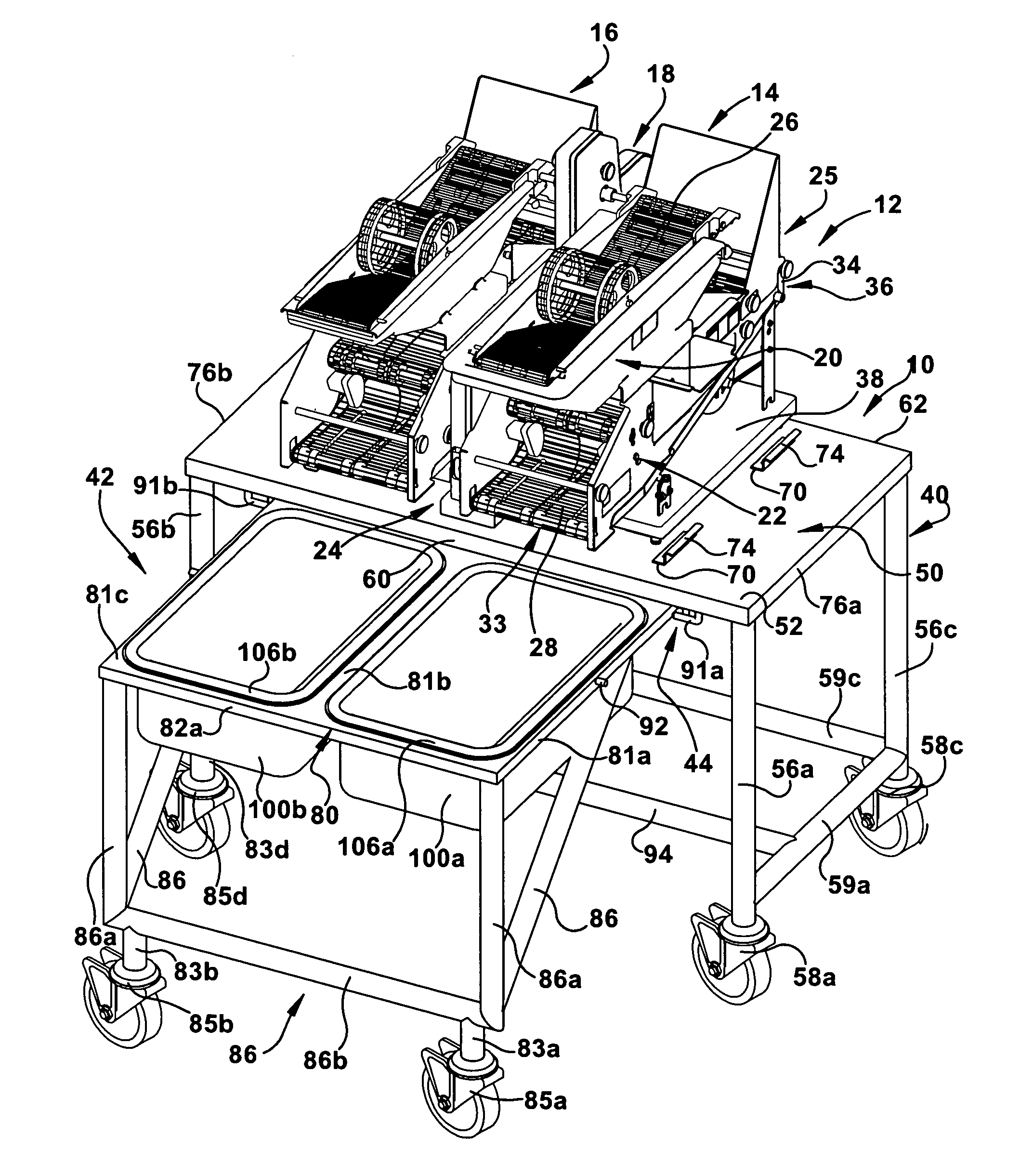
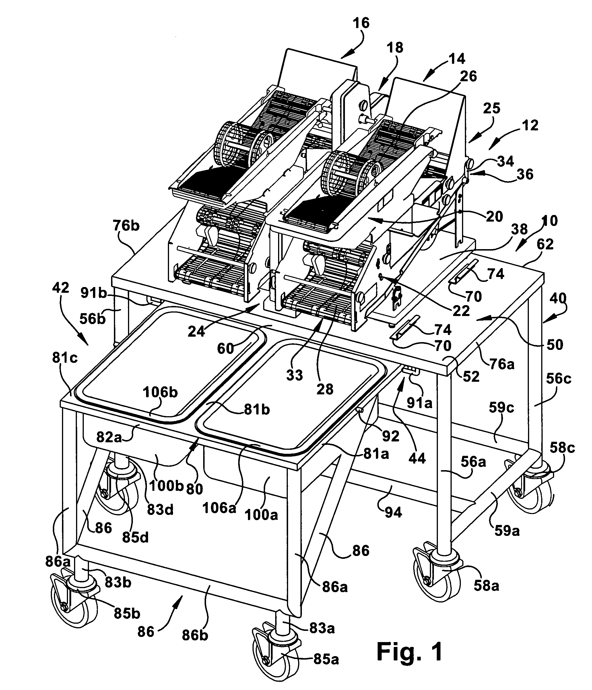
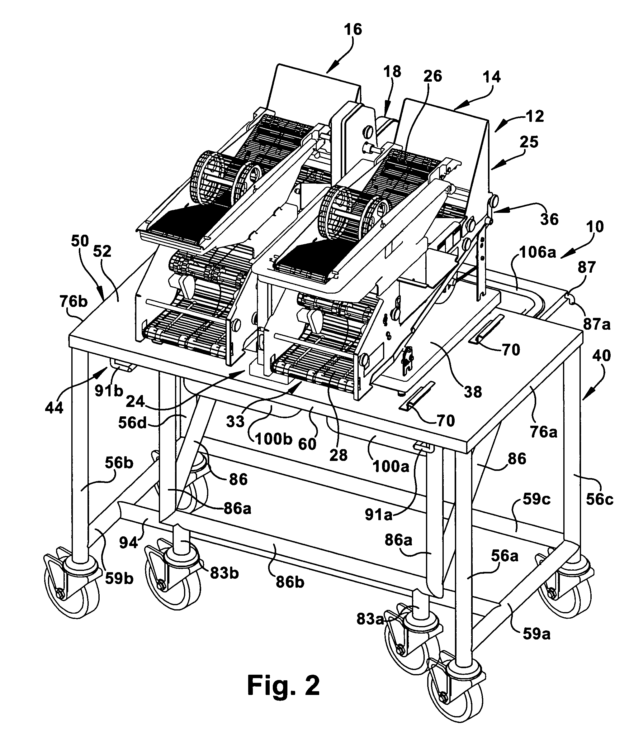
[0027] A support table assembly of the present invention is shown generally at 10 in FIGS. 1 and 2. The support table assembly 10 is adapted to support a food product breading machine 12. The food product breading machine 12 shown in FIGS. 1-6 is a high volume breading and battering machine that includes two parallel breading and battering units 14, 16 whose conveyors are driven by a central drive mechanism 18 located between the two units. It should be understood that the support table assembly 10 of the present invention is not limited to any particular style or configuration of breading machine. Rather, as would be recognized by one of skill in the art, the support table assembly 10 of the present can be modified to fit the size and configuration of any breading machine and is equally applicable to breading machines that include battering units as well as those that do not include battering units.

[0028] The structure and operation of the two parallel breading / battering units 14,...


PUM


Abstract

A support table assembly for a food product breading machine. The support table assembly includes a support table defining an upper support surface for supporting a breading machine, a guide coupled to the support table assembly and a slide assembly that is slidable beneath the support table along the guide between a first and a second position. The slide assembly defines an opening sized to receive a lug. In the first position of the slide assembly, the finished product lug is aligned with a first end of the breading machine such that finished products discharged from the breading machine drop into the lug and, in the second position of the slide assembly, the lug is aligned with a second end of the breading machine such that materials discharged from the breading machine during a cleaning operation drop into the lug.

Description

FIELD OF THE INVENTION [0001] The present invention relates to a support table assembly for a food product breading machine and, more particularly, to a support table assembly for a food product breading machine including a support table and a slide assembly coupled to the support table that supports a breading lug in a selected one of two positions, one position for receiving finished products from the food product breading machine and a second position for receiving discharged material from the breading machine during a cleaning operation. BACKGROUND OF THE INVENTION [0002] Food product breading machines are widely used in restaurants and food processing industry to coat food items such as chicken tenders, fish filets, onion rings, etc., with breading and / or batter prior to frying or baking the items. An example of a food product breading machine is disclosed in U.S. Pat. No. 6,244,170, issued on Jun. 12, 2001 to Whited. The '170 patent is assigned to the assignee of the present i...

Claims


Application Information

Patent Timeline
Patent Type & Authority Applications(United States)
IPC IPC(8): A23B4/02
CPCA23P1/082A23P20/12
Inventor LAMARCHE, JOHN H. D. IISUKEY, JASON ALEXANDERMUNIGA, SCOTT M.WHITED, JEFFREY A.
Owner BETTCHER INDUSTRIES
Why Eureka
Try Eureka