

Constant frequency power supply
- Summary
- Abstract
- Description
- Claims
- Application Information
AI Technical Summary
Benefits of technology
Problems solved by technology
Method used
Image

Examples
Embodiment Construction
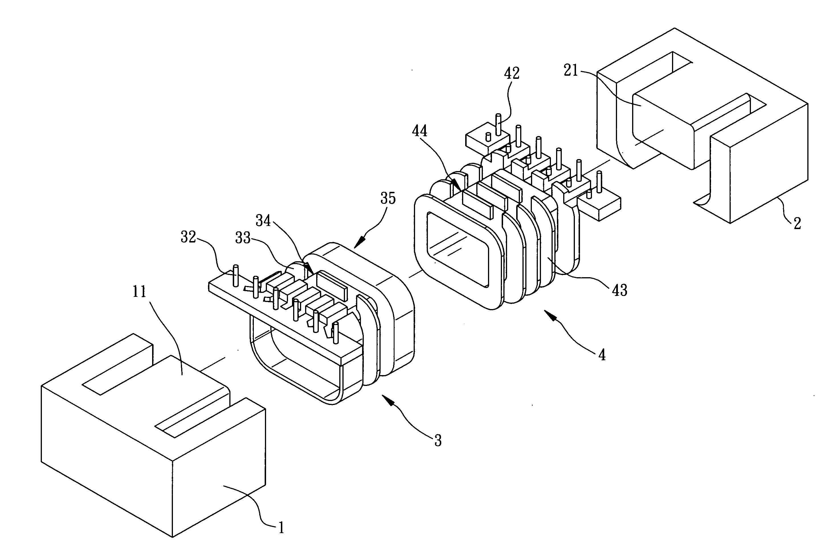
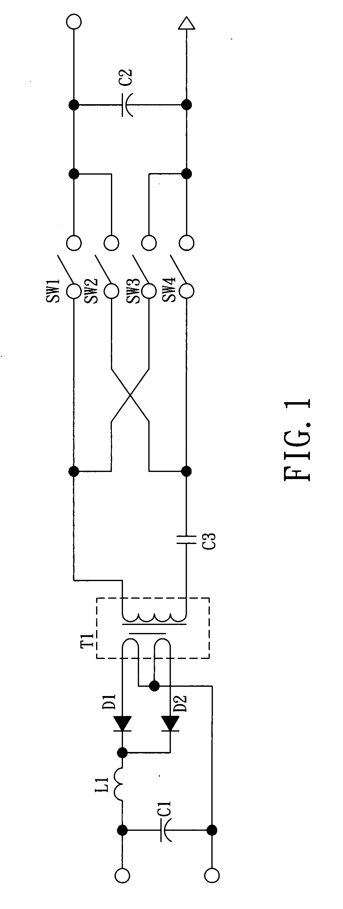
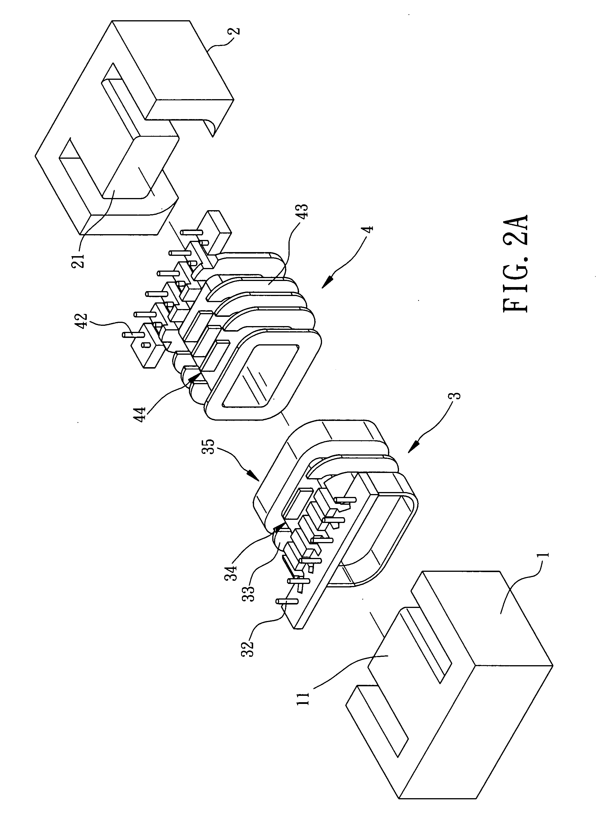
[0016]FIG. 2A is a schematic exploded view of the constant frequency power supply of the invention; and FIG. 2B is a schematic cross-sectional view of the structural combination the constant frequency power supply of the invention; while FIG. 3 is a schematic circuit diagram of the constant frequency power supply applied in whole bridge-type and exchange-type circuit of the invention. As shown in FIG. 2A, FIG. 2B, and FIG. 3, the constant frequency power supply of invention includes a first core 1, a second core 2, a first bobbin 3 and a second bobbin 4. The first core 1 and the second core 2 being disposed in opposite position are made of material with high magnetic permeability. Moreover, The first core 1 and the second core 2 have a first protruded body 11 and a second protruded body 21 respectively that are arranged in a predetermined shape. In a preferred embodiment of the invention, the first protruded body 11 and the second protruded body 21 are arranged in straight line, of ...
PUM
 Abstract
Description
Claims
Application Information