
Cable or the like protecting and guiding device

a technology of protecting and guiding device and cable, which is applied in the direction of hoisting chains, hauling chains, and cables between relatively moving parts, can solve the problems of inability to achieve smooth relative movement of the link frame train, and inability to reduce the device. , to achieve the effect of suppressing the increase of parts, reducing the radius of flexion, and reducing the device siz

Inactive Publication Date: 2011-07-21
TSUBAKIMOTO CHAIN CO
View PDF7 Cites 8 Cited by
  • Summary
  • Abstract
  • Description
  • Claims
  • Application Information

AI Technical Summary

Benefits of technology

The present invention provides a cable protecting and guiding device that can be downsized by reducing the radius of flexion when the device is bent back in the cable longitudinal direction between cable fixing and moving ends. The device includes a large number of link frames with slidable-contact bottom surfaces that smoothly move together in the cable longitudinal direction. The slidable-contact bottom surfaces have a parallelogram shape, which allows for continuous sliding and smooth movement of the link frames. The invention also provides a cable protecting and guiding device with parallelogram slidable-contact bottom surfaces that orient mutually in the same direction or symmetrically with each other, which ensures stable relative movement of the link frames without obliquely moving in the cable longitudinal direction.

Problems solved by technology

As a result, there has been a problem that it is unable to downsize the device due to the increase of the radius of flexion required in bending back the device.
Accordingly, there has been a problem that it is unable to attain smooth relative move of a train of the link frames bent back in the cable longitudinal direction between the cable fixing and moving ends.

Method used


Image

  • Cable or the like protecting and guiding device
  • Cable or the like protecting and guiding device
  • Cable or the like protecting and guiding device

Examples


Embodiment Construction

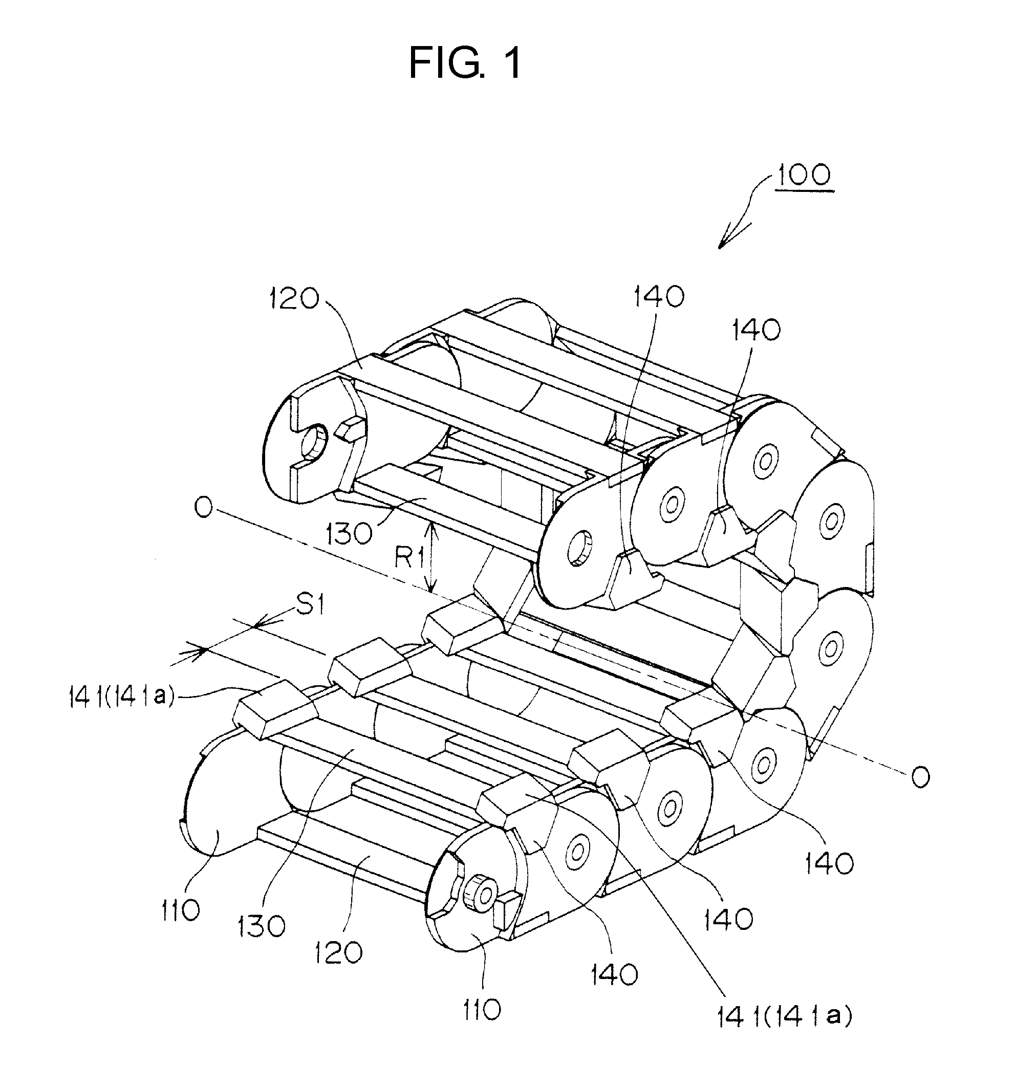
[0032]A first embodiment of a cable protecting and guiding device of the invention will be explained with reference to FIGS. 1 through 11.

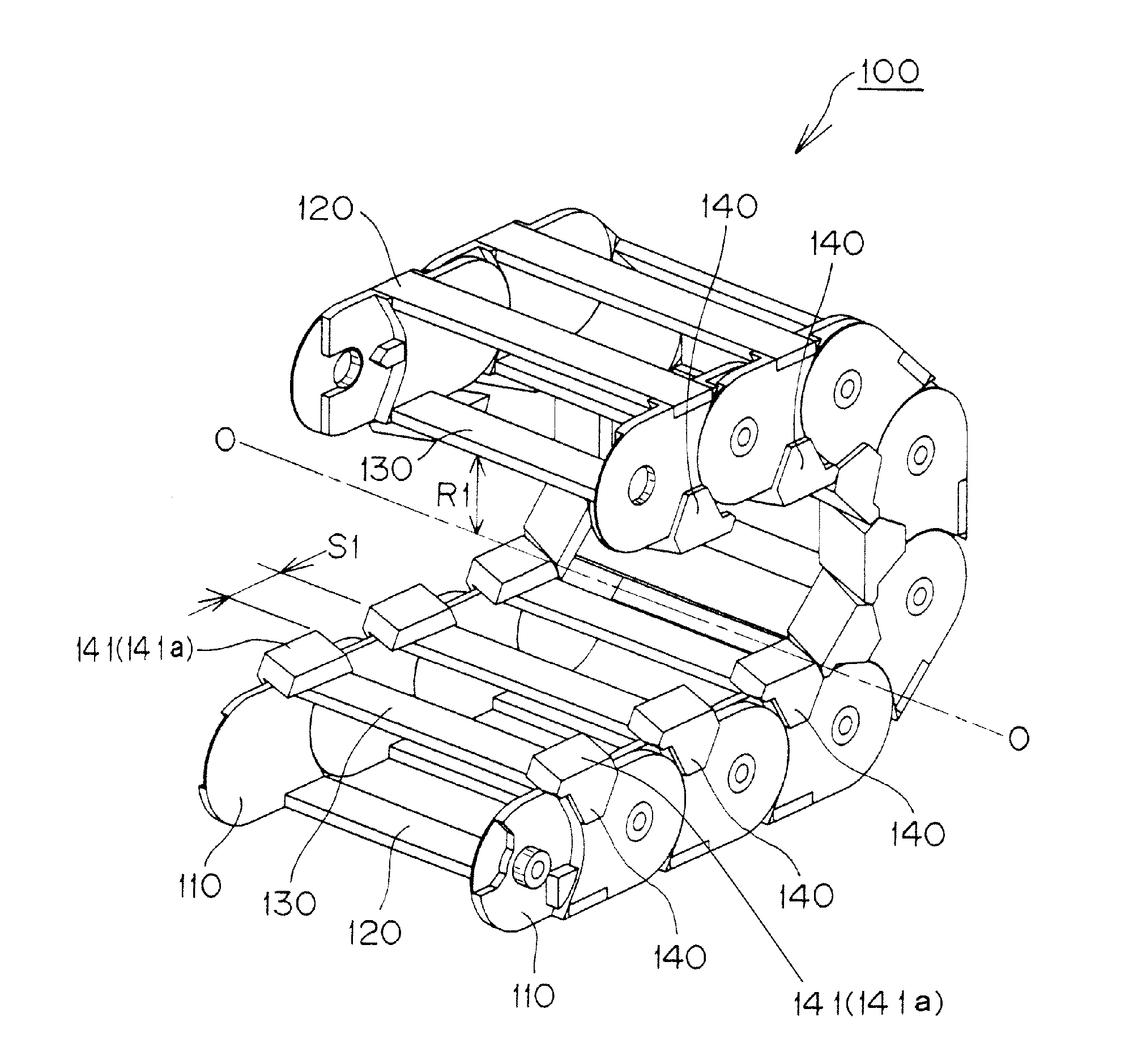
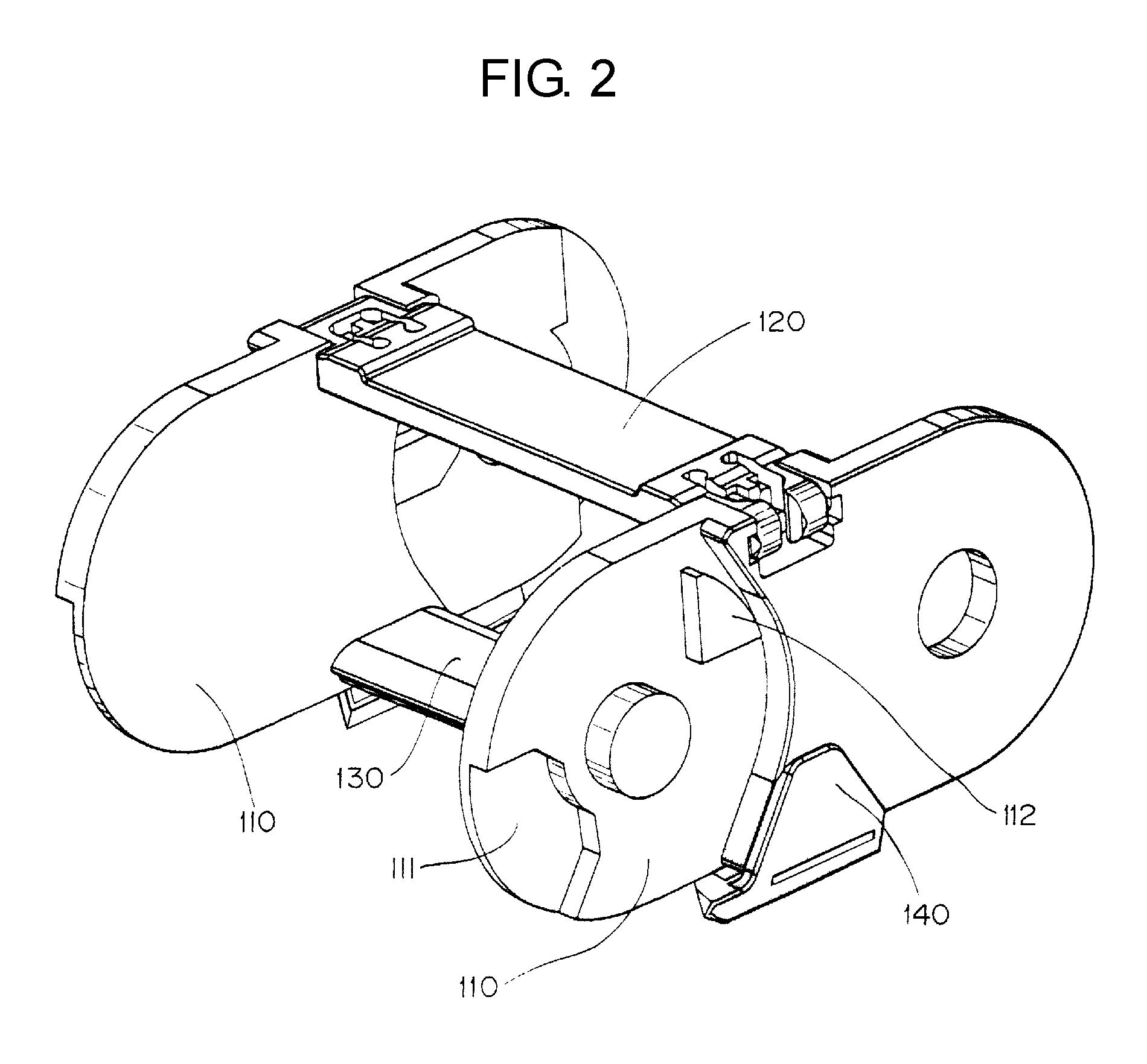
[0033]FIG. 1 is a schematic view showing a flexed state of the cable protecting and guiding device of the first embodiment of the invention, FIG. 2 is an enlarged perspective view of a link frame and a shoe shown in FIG. 1, FIGS. 3A and 3B are perspective views of the shoe shown in FIG. 1, FIG. 4 is a partially cutaway perspective view showing a state of the shoe attached to the link frame shown in FIG. 1, FIG. 5 is a perspective view showing a state how upper and lower shoes of the device of the first embodiment slidably contact, FIG. 6 is a schematic view showing a flexed state of a cable protecting and guiding device of a second embodiment of the invention, FIG. 7 is an enlarged perspective view of a link frame and a shoe shown in FIG. 6, FIGS. 8A and 8B are perspective views showing one shoe shown in FIG. 6, FIGS. 9A and 9B are perspective vie...


PUM


Abstract

The invention provides a cable protecting and guiding device with a reduced radius of flexion formed when the device is bent back in a cable longitudinal direction between cable fixing and moving ends and which attains a smooth movement by continuously sliding along slidable-contact bottom portions of shoes disposed on upper and lower parts of the flexed cable inner peripheral side. A slidable-contact bottom portion of a shoe provided on the flexed cable inner peripheral side of a pair of link plates disposed apart in the lateral direction has a parallelogram slidable-contact bottom surface that slidably contacts between upper and lower shoes on the flexed cable inner peripheral side.

Description

CROSS REFERENCE TO RELATED APPLICATIONS[0001]This application claims the foreign priority benefit under Title 35, United States Code, §119 (a)-(d) of Japanese Patent Application No. 2010-009220, filed on Jan. 19, 2010 in the Japan Patent Office, the disclosure of which is herein incorporated by reference in its entirety.BACKGROUND OF THE INVENTION[0002]1. Field of the Invention[0003]The present invention relates to a protecting and guiding device for a cable or the like. More specifically, the present invention relates to a protecting and guiding device for a cable or the like which securely and steadily protects and guides flexible cables and the like. Examples of cables which may be used in accordance with the present invention include an electrical cable for transmitting electrical signals or supplying power and a hose for supplying hydraulic pressure and air pressure by connecting a mobile part with a stationary part of industrial machines and vehicles.[0004]2. Related Art[0005]...

Claims


Application Information

Patent Timeline
Patent Type & Authority Applications(United States)
IPC IPC(8): H02G11/00
CPCH02G3/0475F16G13/16H02G11/00
Inventor YAMASHITA, KATSUHIDE
Owner TSUBAKIMOTO CHAIN CO
Learn More