Dual-bearing reel

a reel and dual-bearing technology, applied in reels, applications, fishing, etc., can solve the problems of unlikely change of brake mode and disabled operation of the first regulator, and achieve the effects of less variation of magnetic flux density, less varies in magnetic flux density, and efficient shielding

Active Publication Date: 2016-01-21
SHIMANO INC
View PDF7 Cites 5 Cited by
  • Summary
  • Abstract
  • Description
  • Claims
  • Application Information

AI Technical Summary

Benefits of technology

[0026]The first shield member may include a first shield portion and a second shield portion. The first shield portion is disposed on a stepped surface, faced to the spool, of the second cover part. The second shield portion is disposed on the first surface of the circuit board so as to shield a region located on an inner peripheral side of the first shield portion. In this configuration, the first shield member can be divided and disposed on the cover member and the circuit board. Thus, the magnetic flux of the brake magnet can be efficiently shielded by the first shield member.
[0027]The brake unit may further include a second shield member. The second shield member is mounted to at least a part of a second surface, located on an opposite side of the first surface, of the circuit board so as to be disposed at least either between the first magnet and the second detector or between the second magnet and the first detector. In this configuration, at least either of the first and second detectors is unlikely to be affected by the magnet for positional detection. Thus, at least either of the first and second detectors can be further enhanced in accuracy of detection.
[0028]The brake magnet may be polar-anisotropic magnet. In this configuration, the brake magnet is not radial-anisotropic magnet such that N-poles and S-poles are radially aligned, but is polar-anisotropic magnet such that N-poles and S-poles are circumferentially aligned. Thus, a surface magnetic flux density distribution having a sinusoidal wave like pattern is obtained and magnetic flux density less varies. Accordingly, the spool can be enhanced in rotational balance.
[0029]The brake magnet may be mounted to the spool shaft by bonding so as to be unitarily rotatable therewith. In this configuration, a strong force does not act on the brake magnet. Thus, the relatively fragile brake magnet can be easily mounted to the spool shaft without being damaged or broken.

Problems solved by technology

Thus, the operation of the first regulator is disabled when the cover portion is closed.
With this configuration, the brake mode is unlikely to be changed by an erroneous operation of the first regulator.

Method used


Image

  • Dual-bearing reel
  • Dual-bearing reel
  • Dual-bearing reel

Examples


first preferred embodiment

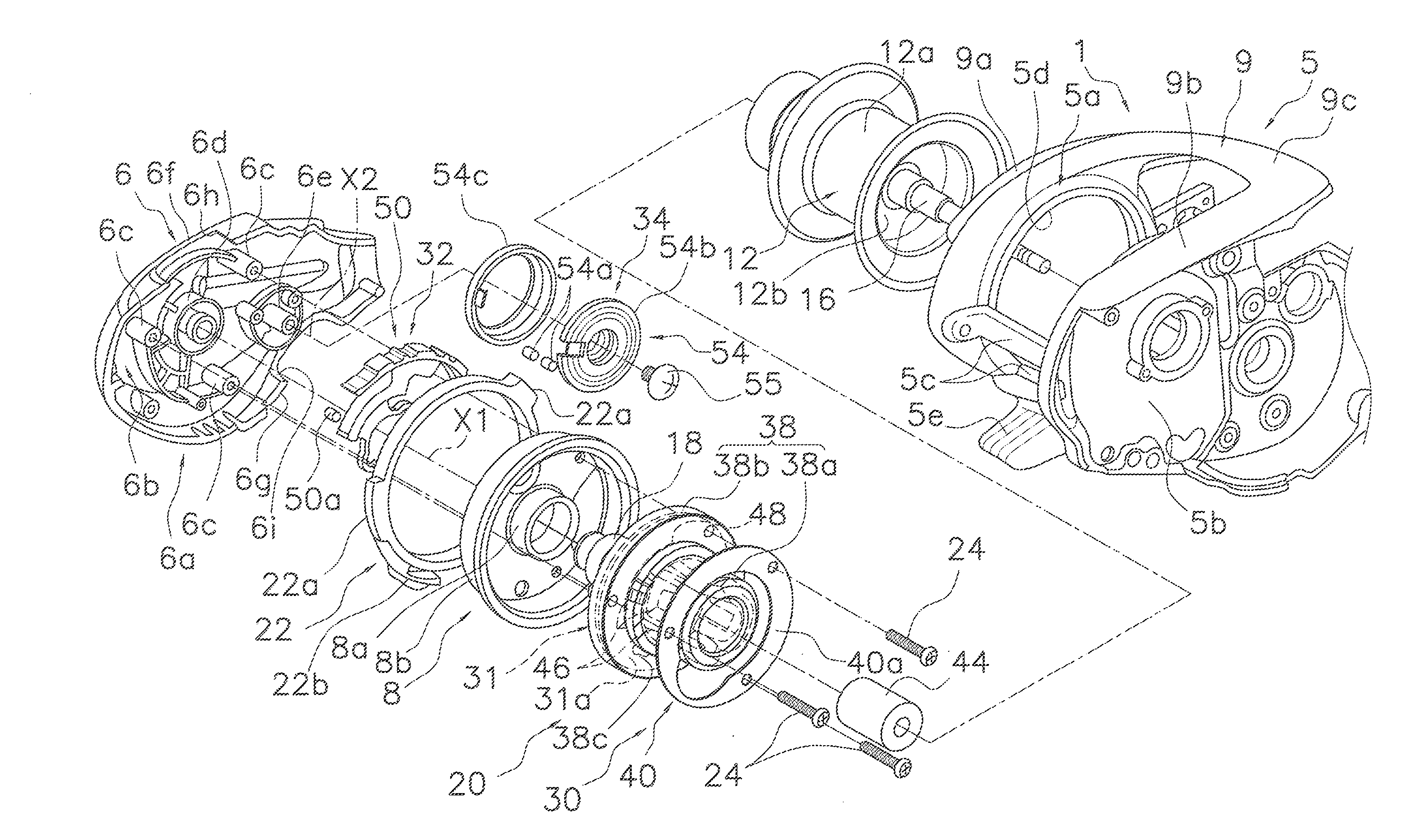
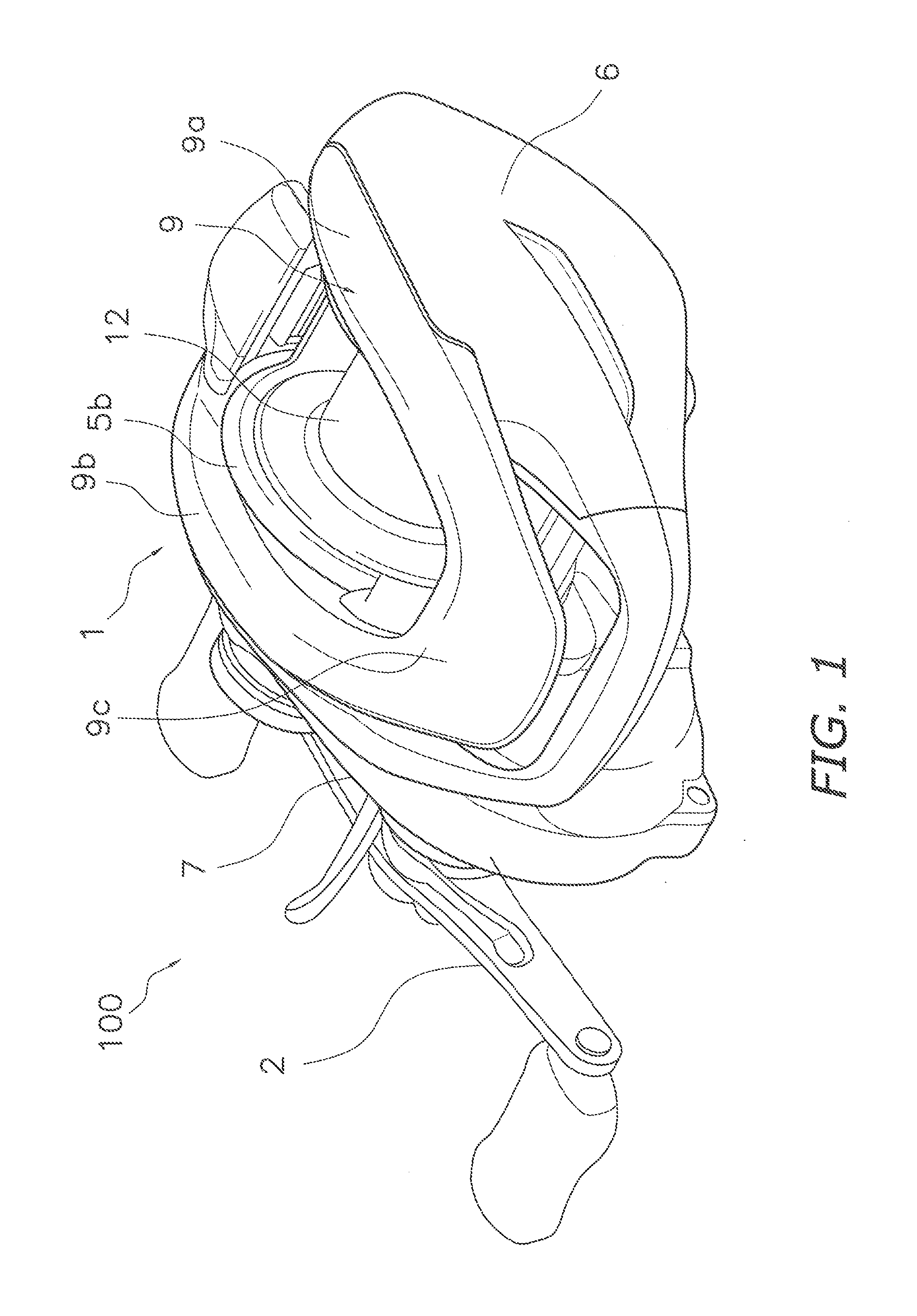
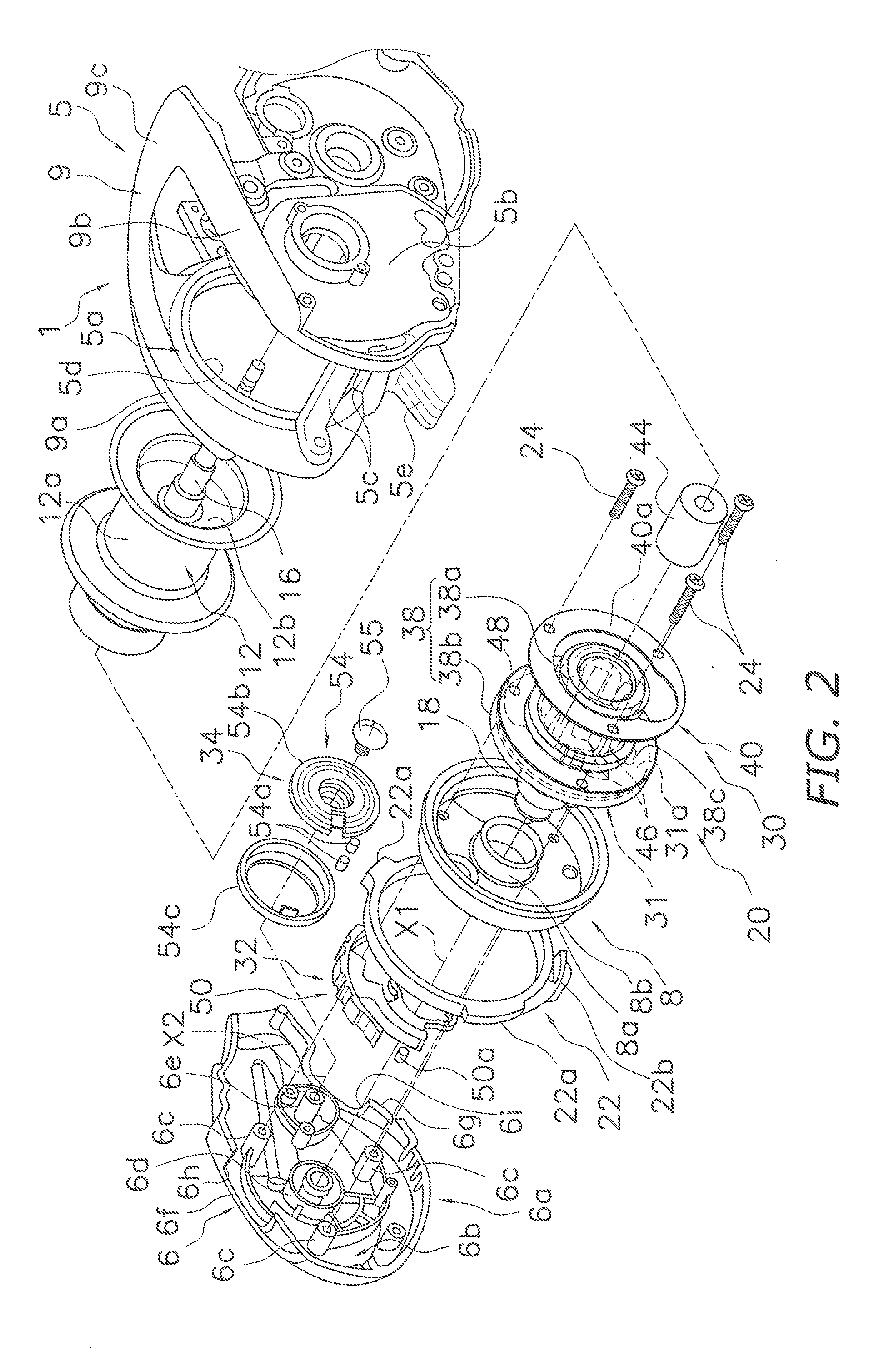
[0047]In FIGS. 1 and 2, a dual-bearing reel 100 according to a first preferred embodiment of the present invention is of a type capable of casting out a fishing line (i.e., reeling out a fishing line in a forward direction). The dual-bearing reel 100 includes a reel body 1, a handle 2, a spool 12, a spool shaft 16 and a brake unit 20 (see FIG. 2). The brake unit 20 is mounted to the reel body 1 and is configured to electrically brake rotation of the spool 12.

[0048]The reel body 1 includes an integrally formed frame 5 and a side cover 7 disposed on the handle 2 side of the frame 5.

[0049]As shown in FIG. 2, the frame 5 includes a first side plate 5a, a second side plate 5b, a plurality of coupling portions 5c and a thumb rest 9. The first side plate 5a is disposed on the opposite side of the handle 2. The second side plate 5b is disposed in opposition to the first side plate 5a. The coupling portions 5c couple the first side plate 5a and the second side plate 5b. The pair of the first...

second preferred embodiment

[0073]In the first preferred embodiment, the first shield member 40 is designed to be mounted between the brake magnet 44 and both of the first detector 52 and the second detector 56. In the present invention, however, the positional arrangement of the first shield member 40 is not limited to the above.

[0074]In a second preferred embodiment shown in FIG. 10, a second shield member 140 is disposed on the second surface 31b of the circuit board 31 so as to be disposed both between the first detector 52 and the second magnets 54a and between the second detector 56 and the first magnets 50a. The second shield member 140 is formed by, for instance, curving an iron plate having a predetermined width (of e.g., roughly 5 mm). The second shield member 140 has a third shield portion 140a and a fourth shield portion 140b. The third shield portion 140a shields transmission of the magnetic fluxes of the second magnets 54a to the first detector 52. The fourth shield portion 140b shields transmiss...

third preferred embodiment

[0075]In a third preferred embodiment of the present invention shown in FIG. 11, a brake portion 230 further includes an O-ring 260 and a compression member 262. The O-ring 260 is contactable to the second end surface 44b. The compression member 262 is fixed to a spool shaft 216, and can compress the O-ring 260 while the O-ring 260 is interposed and held between itself and the second end surface 44b. The O-ring 260 is an exemplary elastic ring. The compression member 262 is an annular member, and has an annular recess 262a on its outer peripheral part in order to attach the O-ring 260. Furthermore, the compression member 262 has a tapered part 262b in its inner peripheral part. The tapered part 262b functions as a disc spring. The inner diameter of the tapered part 262b is slightly smaller than the outer diameter of a part of the spool shaft 216 to which the compression member 262 is mounted. The spool shaft 216 has an annular groove 216a on its part to which the tapered part 262b o...


PUM


Abstract

A dual-bearing reel includes a reel body, a spool rotatably held between side plates, and a brake unit configured to brake the spool. The brake unit includes a cover portion, a first regulator and a second regulator. The cover portion has a first circumferential part and a second circumferential part, and is mounted to the reel body. The first regulator and the second regulator are covered with the cover portion. The first circumferential part has a first opening exposing at least a part of the first regulator therethrough, whereas the second circumferential part has a second opening exposing at least a part of the second regulator therethrough. The reel body has a first restriction part covering the first opening.

Description

CROSS-REFERENCE TO RELATED APPLICATIONS[0001]This application claims priority to Japanese Patent Applications Nos. 2014-146107, 2014-146108 and 2014-146109 filed on Jul. 16, 2014, the entirety of each of which is hereby incorporated by reference.BACKGROUND[0002]1. Field of the Invention[0003]The present invention relates to a dual-bearing reel equipped with a brake unit for braking a spool that is rotatable about a spool shaft with respect to a reel body of the dual-bearing reel.[0004]2. Background Information[0005]In general, conventional dual-bearing reels, especially, bait casting reels capable of releasing a fishing line in casting, are equipped with a brake unit for braking a spool. With this configuration, backlash can be prevented when casting.[0006]A type of brake unit has been known that includes two regulators, i.e., a first regulator and a second regulator, in order to regulate a brake force as minutely as possible (see e.g., Japan Laid-open Patent Application Publication...

Claims


Application Information

Patent Timeline
Patent Type & Authority Applications(United States)
IPC IPC(8): A01K89/0155A01K89/015A01K89/033
CPCA01K89/01555A01K89/0193A01K89/045A01K89/01931A01K89/015
Inventor NIITSUMA, AKIRAUMEZAWA, YOSHIOFUJII, SATOSHIFUJIWARA, TAKESHIMARUOKA, TAKANORI
Owner SHIMANO INC
Why Eureka
Try Eureka