Illumination assembly, method for providing a radiation beam, lithographic projection apparatus and device manufacturing method

a technology of lithographic projection and assembly, which is applied in the field of lithographic apparatus, can solve the problems of unfavorable lithographic projection of patterning devices on substrates, negative effects on the projection of patterning devices, and need to be arranged and adjusted specially for a specific source, and achieves the effect of simple and cost-effective way, easy adjustment, and convenient adjustmen

Inactive Publication Date: 2005-12-08
ASML NETHERLANDS BV
View PDF7 Cites 5 Cited by
  • Summary
  • Abstract
  • Description
  • Claims
  • Application Information

AI Technical Summary

Benefits of technology

[0025] According to an embodiment of the invention the beam splitter is formed by an axicon, comprising a first part and a second part. The axicon is preferably a linear wedge-shaped axicon. This is a simple and cost effective way of providing a beam splitter, that can easily be adjusted to provide two separate beams with a predetermined distance.
[0026] According to an embodiment of the invention an intermediate distance between the first part and the second part is adaptable for adjusting the distance between the split radiation beams in at least one of the second and third direction. This is an easy method to adjust the distance between the split radiation beams.
[0027] According to an embodiment of the invention the axicon is rotatable with respect to the first direction, for splitting the radiation beam in either the second or the third direction. By rotating the beam splitter, the direction in which the received radiation beams are split can easily be adjusted.

Problems solved by technology

Further, since the divergence in the x direction is different from the divergence in the y direction, this also results in an uneven light distribution in the pupil plane.
This has negative effects on the projection of the patterning device on the substrate as will be understood by a person skilled in the art.
It might for instance result in uneven imaging results on the substrate for pattern lines elongated in both the x and y direction.
The disadvantage of the solutions presented in U.S. Pat. No. 6,583,855 B2 is that all need to be arranged and adjusted specially for a specific source.
It will be appreciated by a person skilled in the art that the same increase in divergence could be obtained by lowering the magnification factor of the beam expander and thereby decreasing the outer dimensions of the beam, but this has a major disadvantage as will be outlined below.
A difference in beam size in x and y will therefore result in a difference in polewidth in x and y, which would result in the undesired situation of different imaging characteristics for patterns oriented in the x and y direction.

Method used


Image

  • Illumination assembly, method for providing a radiation beam, lithographic projection apparatus and device manufacturing method
  • Illumination assembly, method for providing a radiation beam, lithographic projection apparatus and device manufacturing method
  • Illumination assembly, method for providing a radiation beam, lithographic projection apparatus and device manufacturing method

Examples


Embodiment Construction

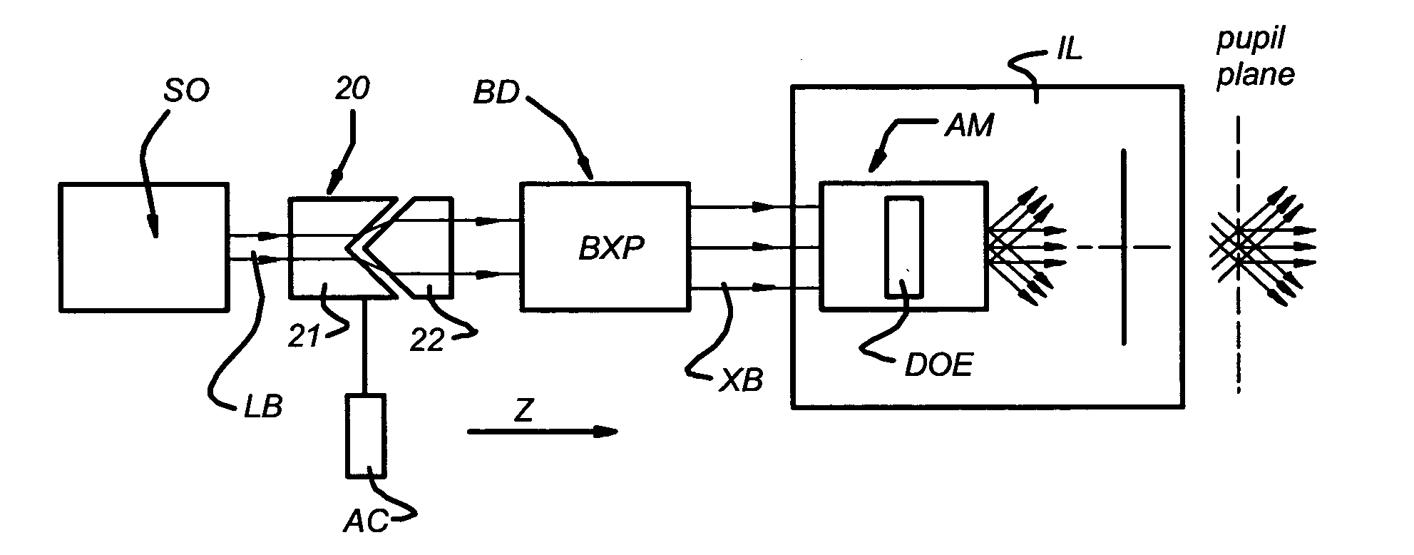
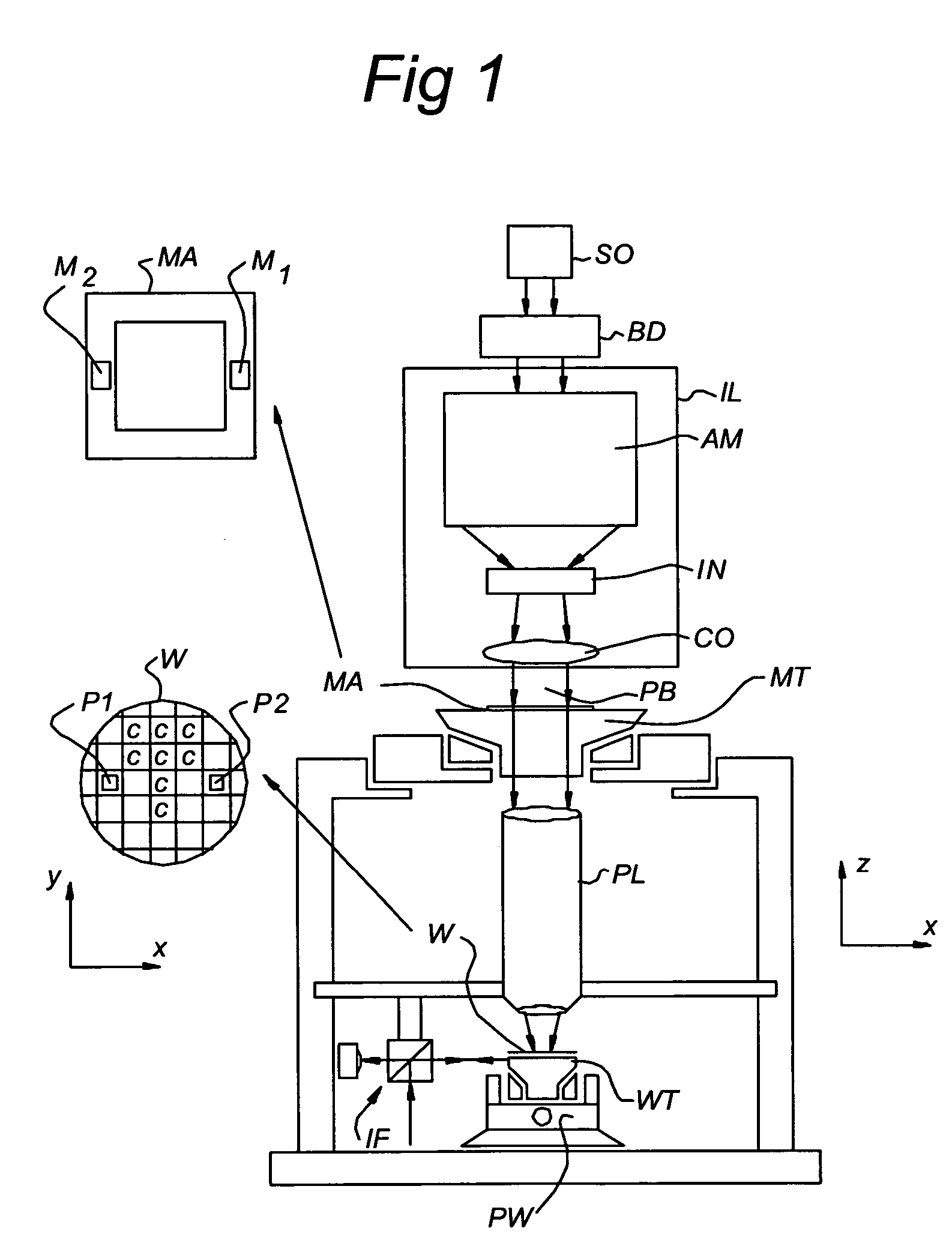
[0068]FIG. 1 schematically depicts a lithographic apparatus according to a particular embodiment of the invention. The apparatus comprises: [0069] an illumination system (illuminator) IL for providing a projection beam PB of radiation (e.g. UV radiation). [0070] a first support structure (e.g. a mask table) MT for supporting a patterning device (e.g. a mask) MA and connected to first positioner PM for accurately positioning the patterning device with respect to item PL; [0071] a substrate table (e.g. a wafer table) WT for holding a substrate (e.g. a resist-coated wafer) W and connected to second positioner PW for accurately positioning the substrate with respect to item PL; and [0072] a projection system (e.g. a refractive projection lens) PL for imaging a pattern imparted to the projection beam PB by patterning means MA onto a target portion C (e.g. comprising one or more dies) of the substrate W.

[0073] As here depicted, the apparatus is of a transmissive type (e.g. employing a tr...


PUM

PropertyMeasurementUnit
wavelengthaaaaaaaaaa

Abstract

The invention relates to an illumination assembly, including a beam expander being arranged for receiving from a radiation source a radiation beam directed in a first direction (z) and for expanding the beam with a first magnification factor in a second direction (x) and with a second magnification factor in a third direction (y). The first, second and third directions being substantially mutually orthogonal. The illumination assembly further includes a beam splitter that is arranged for splitting the radiation beam in two split radiation beams split in at least one of the second and third direction, the propagation direction of the split radiation beams being substantially in the first direction. The beam splitter is further arranged for delivering the split radiation beams to the beam expander, of which at least one of the magnification factors is adjustable.

Description

FIELD OF THE INVENTION [0001] The present invention relates generally to lithographic apparatus and more particularly to such apparatus incorporating an illumination assembly and methods for their use. BACKGROUND OF THE INVENTION [0002] A lithographic apparatus is a machine that applies a desired pattern onto a target portion of a substrate. Lithographic apparatus can be used, for example, in the manufacture of integrated circuits (ICs). In that circumstance, a patterning device, which is alternatively referred to as a mask or a reticle, may be used to generate a circuit pattern corresponding to an individual layer of the IC, and this pattern can be imaged onto a target portion (e.g. comprising part of, one or several dies) on a substrate (e.g. a silicon wafer) that has a layer of radiation-sensitive material (resist). In general, a single substrate will contain a network of adjacent target portions that are successively exposed. Known lithographic apparatus include so-called steppe...

Claims


Application Information

Patent Timeline
Patent Type & Authority Applications(United States)
IPC IPC(8): G02B5/00G02B27/10G03B27/54G03F7/20H01L21/027
CPCG03F7/70141G03F7/70158
Inventor BOTMA, HAKO
Owner ASML NETHERLANDS BV
Why Eureka
Try Eureka