Method for determining the absolute position of a linear actuator

a linear actuator and absolute position technology, applied in the direction of electronic commutators, brake systems, instruments, etc., can solve the problems of affecting the reliability of the system, affecting the accuracy of the absolute position of the actuator, and both methods have disadvantages, so as to achieve the effect of easy and cost-effective operation

Inactive Publication Date: 2015-11-05
CONTINENTAL TEVES AG & CO OHG
View PDF2 Cites 1 Cited by
  • Summary
  • Abstract
  • Description
  • Claims
  • Application Information

AI Technical Summary

Benefits of technology

[0024]The method according to an aspect of the invention can be carried out easily and cost-effectively. Only one second sensor is necessary. Structural measures when ensure that the actuator is located at a known position at the system start are not necessary. Furthermore there is no need to carry out a reference run at the system start.

Problems solved by technology

However, both methods have disadvantages.
This leads to restrictions on the system availability and to the need to reliably rule out external influences on the reference run.

Method used


Image

  • Method for determining the absolute position of a linear actuator
  • Method for determining the absolute position of a linear actuator

Examples


Embodiment Construction

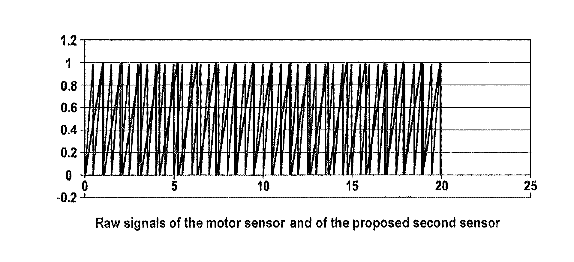
[0028]In the exemplary embodiment described here, the first sensor (rotor position sensor) is seated centrally on the motor shaft and has a gearwheel with 20 teeth. A second sensor, the transmitter wheel of which has 42 teeth and meshes with the gearwheel of the first sensor, is arranged parallel next to this first sensor. The second sensor is therefore coupled to the first sensor with a transmission ratio of i=1:2.1.

[0029]The corresponding sensing of the gearwheels occurs by means of magnets. The evaluation of the signals is carried out by means of circuit boards with two sensor / ICs.

[0030]In another embodiment, the angular position of the gearwheels is determined by measuring the direction of the emitted magnetic field of magnets, which are connected in a positively locking fashion to the gearwheels, by means of two magnetic sensors (preferably MR sensors).

[0031]FIG. 1 illustrates the raw signals of the rotor sensor (first sensor) and of the second sensor which present the profile ...


PUM


Abstract

A method for determining the absolute position of a linear actuator is described. In the process, the rotational angle position of the rotor of the corresponding electric motor of the linear actuator is determined by a first sensor. In addition, the rotary angle position of a transmitter wheel of a second sensor coupled to the rotor is determined by means of a special transmission ratio. The absolute position of the linear actuator is derived from the differential value of the determined rotary angle positions. The method can be implemented in a simple and inexpensive manner.

Description

CROSS REFERENCE TO RELATED APPLICATIONS[0001]This application is the U.S. National Phase Application of PCT / EP2012 / 073880, filed Nov. 28, 2012, which claims priority to German Patent Application No. 10 2011 089 820.4, filed Dec. 23, 2011, the contents of such applications being incorporated by reference herein.FIELD OF THE INVENTION[0002]The present invention relates to a method for determining the absolute position of a linear actuator.BACKGROUND OF THE INVENTION[0003]In many electromechanically activated systems, in particular brake systems, linear actuators are used which have, in addition to the actual actuator element, an electric motor and at least one transmission which is connected downstream for driving the actuator element. An example of such a transmission is a ball screw drive.[0004]When operating such systems it is necessary to know, in addition to the movement path of the linear actuator, the absolute position thereof. The use of a linearly measuring actuator position ...

Claims


Application Information

Patent Timeline
Patent Type & Authority Applications(United States)
IPC IPC(8): G01B21/22
CPCG01B21/22H02P6/16H02P6/006G01D5/2452B60T13/746G01D2205/26
Inventor BOHM, JURGENBESIER, MARCOKAUFMANN, TOMSTAUDER, PETERSCHIRLING, ANDREAS
Owner CONTINENTAL TEVES AG & CO OHG
Why Eureka
Try Eureka