
Tank outlet having a vortex breaker and method for mounting a vortex breaker on the tank outlet of a tank

a technology of vortex breaker and tank outlet, which is applied in the direction of construction, thin material handling, sewer systems, etc., can solve the problems of reducing the liquid throughput of the tank outlet, and achieve the effect of easy purification, easy transportation, and cost-effectiveness

Active Publication Date: 2021-02-02
GEA TUCHENHAGEN GMBH
View PDF18 Cites 0 Cited by
  • Summary
  • Abstract
  • Description
  • Claims
  • Application Information

AI Technical Summary

Benefits of technology

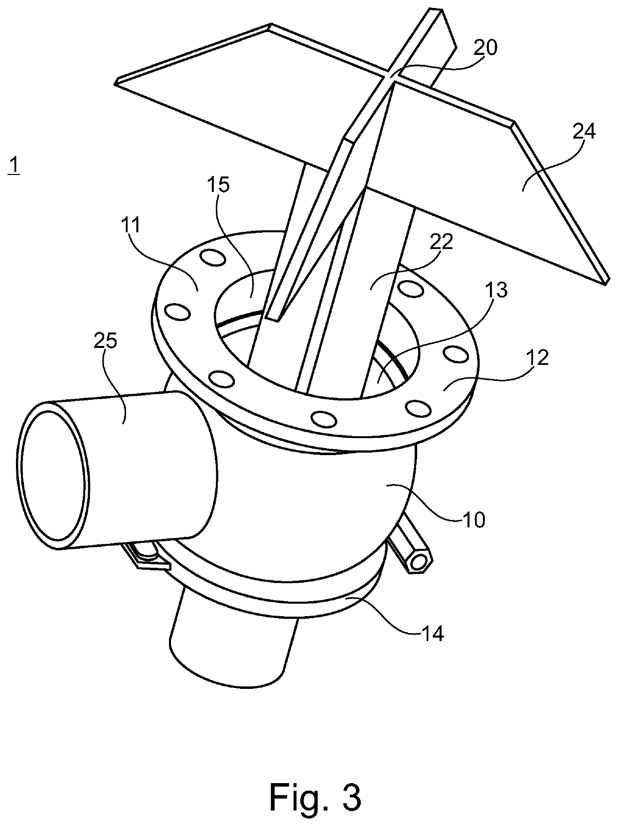
[0014]The outlet region is part of the pressure-tested tank. Via the outlet region, easy and safe connection of the tank with the tube fitting body is ensued. Such a tube fitting body may for example be a commercially available VARIVENT® corner housing having a corresponding inlet region. Preferably, the inlet region and the outlet region are screwed to one another, such that structural modifications to the tank are not required. Moreover, such a connection is releasable and besides the mounting means for the connection, no additional mounting means are required on the tank.
[0035]Mounting a tube fitting body on a tank with the aid of an inlet region allows for a pressure-resistant connection and a direct mounting on an existing outlet region of a tank. The connection between the tank and the tube fitting body may be carried out easily, cost-effectively and without additional effort. Inserting a vortex breaker through the outlet opening in the outlet region of the tank and the inlet opening in the inlet region of the tube fitting body inside the tank allows for the use of vortex breakers with large dimensions. By mounting the vortex breaker solely on the tube fitting body, such that the vortex breaker extends through the inlet region into the tank and does not touch the tank, a sanitary and easily purifiable arrangement of the vortex breaker is enabled. By means of the described method, easy mounting of the vortex breaker into an existing tank outlet is enabled. Moreover, by means of inserting the vortex breaker as described, the formation of vortices is prevented in a large region both in the outlet itself as well as in the tank in front of it, in order to ensure sanitary purification of the tank outlet, also with the vortex breaker being built in.

Problems solved by technology

A structural modification of a pressure tank usually requires a further pressure test, which may be cost-intensive.
In addition to this, gas that is drawn into the tank outlet reduces liquid throughput.

Method used


Image

  • Tank outlet having a vortex breaker and method for mounting a vortex breaker on the tank outlet of a tank
  • Tank outlet having a vortex breaker and method for mounting a vortex breaker on the tank outlet of a tank
  • Tank outlet having a vortex breaker and method for mounting a vortex breaker on the tank outlet of a tank

Examples


Embodiment Construction

[0044]Below, preferred embodiments of the present invention will be described in detail with reference to the enclosed figures.

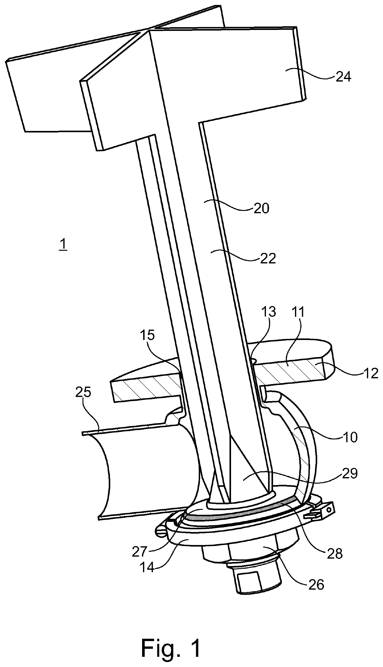
[0045]FIG. 1 shows a first embodiment of the tank outlet 1 with vortex breaker 20 according to the invention. The vortex breaker 20 essentially comprises a head region 24 located on the inside of the tank and a foot region 22 which the vortex breaker 20 is solely mounted to. In the shown embodiment, the vortex breaker 20 is designed as one piece. However, the vortex breaker 20 may also be assembled of two or more parts forming head region 24 and foot region 22. The material of the vortex breaker 20 preferably is a hard synthetic material or a metal, to withstand the occurring flow forces.

[0046]The foot region 22 of the vortex breaker 20 essentially divides the inlet opening 13 into four regions of the same size, through which the content of the tank may stream from the head region 24 towards the cavity of the tube fitting body 10. The same distribution is ca...


PUM

PropertyMeasurementUnit
diameteraaaaaaaaaa
anglesaaaaaaaaaa
angleaaaaaaaaaa

Abstract

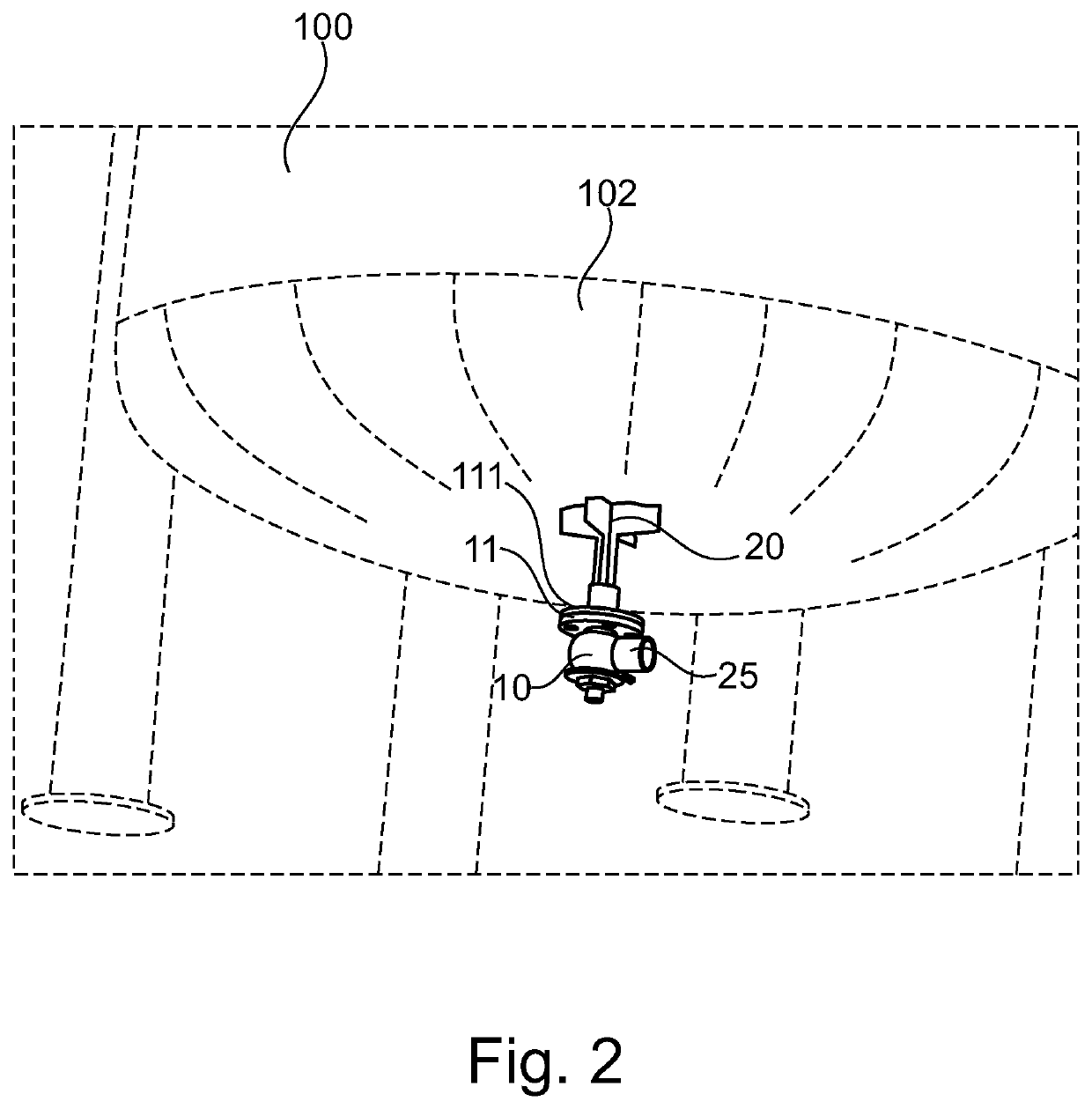
A tank outlet (1) of a tank (100) comprising a tube fitting body (10), with an inlet region (11), which can be mounted on an outlet region (111) of a tank (100), a vortex breaker (20), which is mounted solely on the tube fitting body (10), wherein the vortex breaker (20) extends into the tank (100) through the inlet region (11) and does not touch the tank (100). Moreover, a method for mounting a corresponding vortex breaker (20) on a tank outlet (1) of a tank (100) is claimed.

Description

1. TECHNICAL FIELD[0001]The present invention relates to a tank outlet with a vortex breaker and to a method for mounting the vortex breaker in a tank outlet of a tank. The tank may be a liquid tank as preferably used in food industries.2. PRIOR ART[0002]Tanks, in particular liquid tanks, are used for storing liquids, suspensions or other fluids, for example for storing beer or its intermediate products in a brewery. The tanks are usually designed for accommodating large amounts of a liquid, which can additionally be pressurized. Thus, the tanks must provide a high compressive strength and comply with acknowledged standards. The proof is carried out by means of so-called pressure tests, which have to be repeated after each significant change to the structure of the tank in order to guarantee safety of the tank. A structural modification of a pressure tank usually requires a further pressure test, which may be cost-intensive. Such structural modifications for example include welding ...

Claims


Application Information

Patent Timeline
Patent Type & Authority Patents(United States)
IPC IPC(8): E03F5/10C12C13/00C12H1/22
CPCC12C13/00C12H1/22E03F5/106Y10T137/86348
Inventor DUTSCHMANN, DEANKLEMME, CHRISTIANBUMESTER, BERND
Owner GEA TUCHENHAGEN GMBH
Learn More