Timing element for a lubricant dosing unit, lubricant dosing unit, and method for dosing a lubricant

a lubricant and dosing unit technology, applied in the direction of machines/engines, liquid transfer devices, auxillary lubrication, etc., can solve the problems of contamination of the lubricant used of the components, wet components of bores, etc., and achieve the effect of reducing the cleaning outlay of bores and improving quality

Inactive Publication Date: 2006-04-13
AIRBUS OPERATIONS GMBH
View PDF14 Cites 0 Cited by
  • Summary
  • Abstract
  • Description
  • Claims
  • Application Information

AI Technical Summary

Benefits of technology

[0012] Minimum quantity dosing of lubricant may be possible using a timing element according to the present invention, since lubricant is only provided during a duration of a compressed air pulse of the timing element. In advantage is that empty sucking of supply lines may be prevented, because the shutoff valve is only in an open state during the presence of a compressed air pulse. If no compressed air pulse is provided by the timing element, i.e., if the second piston closes the exit, the shutoff valve may be placed in a closed state and no lubricant may be suctioned out of the supply lines and through the shutoff valve. In other words, the shutoff valve may be blocked in the unpressurized state and may only open upon activation by the compressed air pulse from the timing element. Furthermore, it may be ensured using the lubricant dosing unit that the lubricant dosing is terminated before ending the boring process.
[0013] The timing element may be coupled with known lubricant pumps and integrated into a lubricant supply and dosing system. A further advantage of the timing element may be that it may be designed as a purely pneumatic control system. Therefore, no electronic components may be necessary and the pneumatic control system may be designed in an especially simple and cost-effective way. Wetting of the depression of a bore with lubricant may also be avoided using the lubricant dosing unit according to the present invention, by which additional cleaning outlay may be dispensed with
[0022] Using such a design of the coupling between timing element, lubricant pump, and shutoff valve, it may be possible to ensure easily that during a boring process, no lubricant is suctioned out of supply lines, for example, between the lubricant pump and the shutoff valve. The shutoff valve may be set up in such a way that it may be only opened during the duration of the compressed air pulse, and may be closed when no compressed air pulse is applied.
[0024] By providing a lubricant channel in the plunger bushing, which lubricant channel has a partial area, i.e., a section, having a first diameter and a second partial area having a second diameter, the first diameter being larger than the second diameter, it may be easily possible to produce a fine lubricant jet and / or a lubricant mist, which may be sprayed onto cutting edges of a boring tool which may be positioned within the plunger bushing. By such a design it may be possible to provide the lubricant in a finely and evenly distributed way during the boring, through which the quality of the bore may be improved further.

Problems solved by technology

However, spraying the lubricant from the outside and through the tools results in wetting of the components which are bored.
Further contamination by the lubricant used of the components which are bored occurs in this way.

Method used


Image

  • Timing element for a lubricant dosing unit, lubricant dosing unit, and method for dosing a lubricant
  • Timing element for a lubricant dosing unit, lubricant dosing unit, and method for dosing a lubricant
  • Timing element for a lubricant dosing unit, lubricant dosing unit, and method for dosing a lubricant

Examples


Embodiment Construction

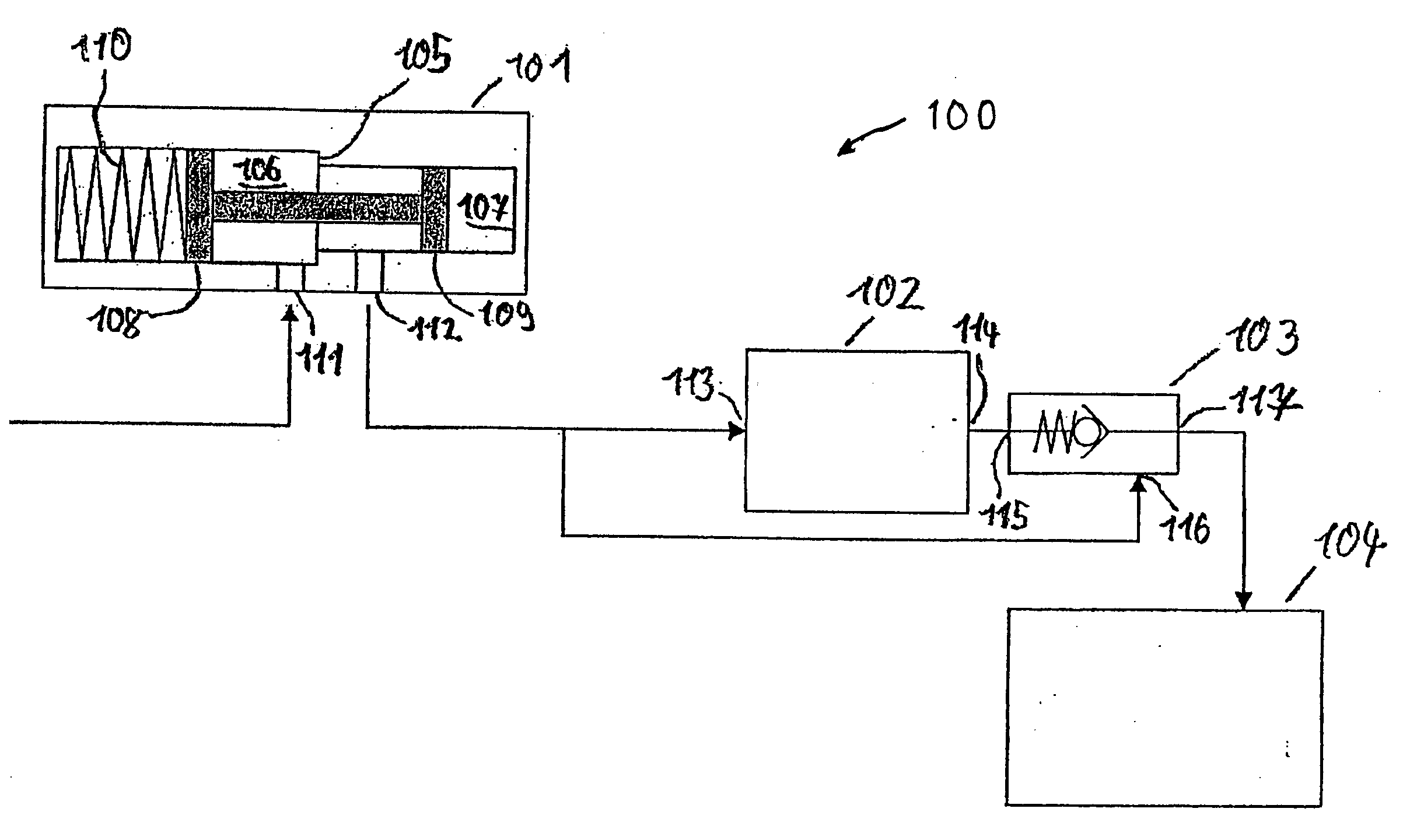
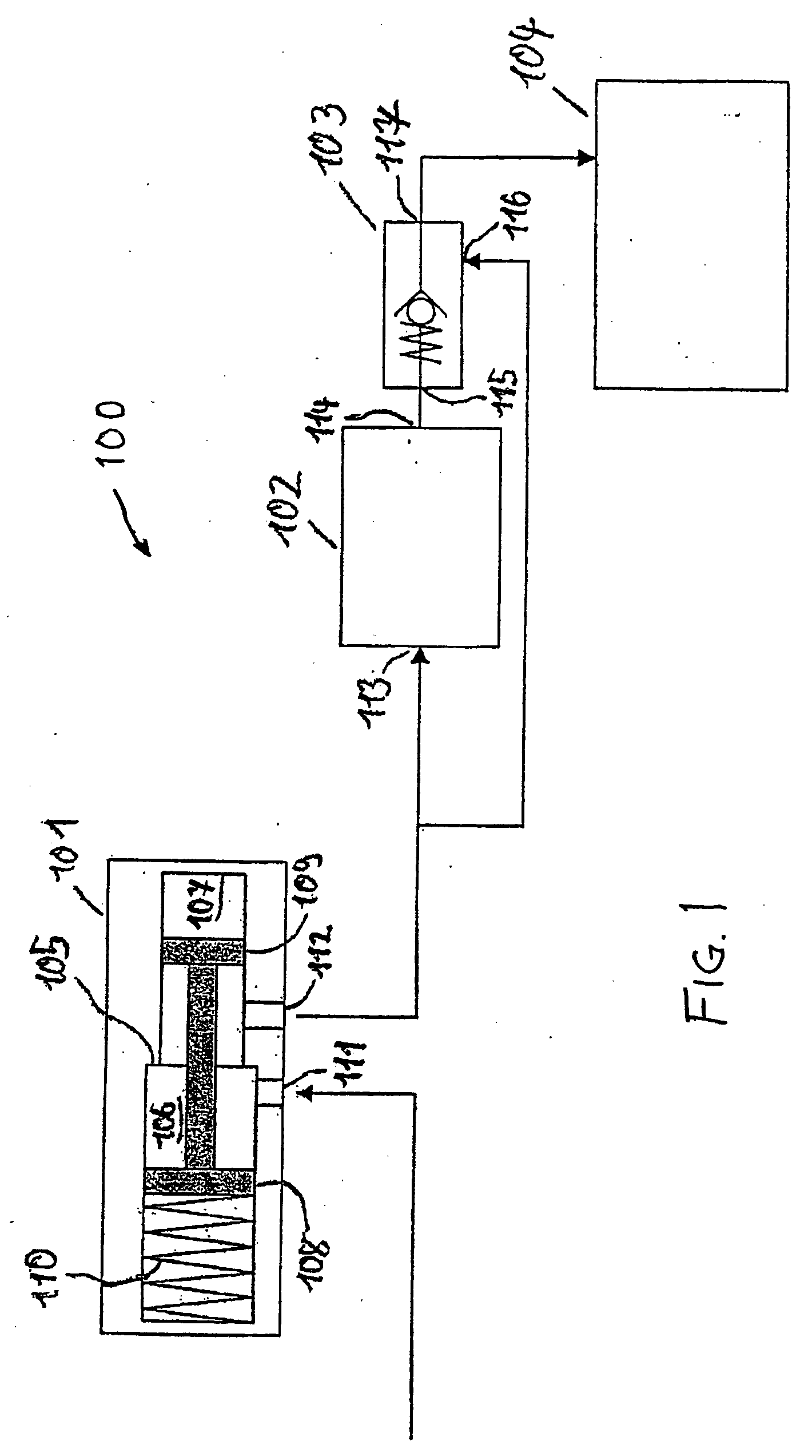
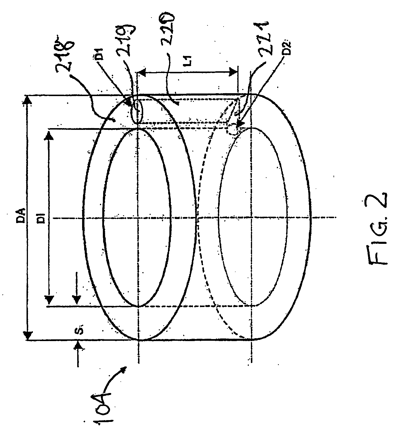
[0031]FIG. 1 schematically illustrates one example of a lubricant dosing unit 100, which comprises a timing element 101, a lubricant pump 102, a pneumatic shutoff valve 103, and a plunger bushing 104 having a lubricant channel, which plunger bushing is illustrated in more detail in FIG. 2.

[0032] The timing element 101 comprises a cavity 105, which comprises a first partial cavity 106 having a round cross-section and a second partial cavity 107 having a round cross-section. A first piston 108 and a second piston 109, which are connected to one another, are positioned within the cavity 105. The first piston 108 has a first diameter, which corresponds to the diameter of the first partial cavity 106, and is positioned inside the first partial cavity 106. The second piston 109 has a second diameter, which corresponds to the diameter of the second partial cavity 107, and is positioned inside the second partial cavity 107. Furthermore, a spring 110 is positioned in the first partial cavit...


PUM

PropertyMeasurementUnit
timeaaaaaaaaaa
diameter D2aaaaaaaaaa

Abstract

A timing element for a lubricant supply system is capable of using pneumatics for the time of delivery of lubricant for a preset duration. In one example, the timing element has a cavity having an entrance and an exit, a first piston and a second piston. The first piston and the second piston are disposed in the cavity. The first piston is coupled to the second piston in such that compressed air in the entrance of the cavity is capable of moving the second piston and closing the exit. A pneumatic timing element may be incorporated into a dosing unit that is capable of supplying an amount of lubricant in a mist to a plunger bushing of a machine tool without. The duration of the dosing may be controlled solely by pneumatics and may prevent excess pooling of lubricant in bore holes by shutting off lubricant delivery at a preset time.

Description

RELATED APPLICATIONS [0001] This application claims the benefit of the filing date of U.S. Provisional Patent Application No. 60 / 616,826 filed Oct. 7, 2004, and of German Patent Application No. 10 2004 048 950.5 filed Oct. 7, 2004 the disclosures of which are hereby incorporated by reference herein.FIELD OF THE INVENTION [0002] The field relates to a timing element for a lubricant dosing unit, a lubricant dosing unit, and a method for dosing a lubricant. BACKGROUND [0003] Machines and drill feed units, particularly for boring metal parts, are known in the related art. Lubricants are frequently used to improve the boring quality, which are typically sprayed onto the tool of the drill feed unit from the outside. The lubricant is typically sprayed for this purpose with the aid of so called minimum quantity dosing systems, using which the quantity of sprayed lubricant may be kept as low as possible. [0004] Furthermore, systems are also known for performing cutting bores, in which the lu...

Claims


Application Information

Patent Timeline
Patent Type & Authority Applications(United States)
IPC IPC(8): F01M11/02F01M1/04
CPCF16N7/38Y10T408/03Y10T408/46Y10T137/7728
Inventor ENDE, WOLFGANGSCHUELER, HARALD
Owner AIRBUS OPERATIONS GMBH
Why Eureka
Try Eureka