
Organic el device and method for producing organic el device

Active Publication Date: 2013-10-31
KANEKA CORP
View PDF4 Cites 6 Cited by
  • Summary
  • Abstract
  • Description
  • Claims
  • Application Information

AI Technical Summary

Benefits of technology

The present invention provides an organic EL device and a method for producing it that simplifies the production process and reduces the device size.

Problems solved by technology

Consequently, when a commercial AC voltage is applied to organic EL elements, the organic EL elements light up at a half cycle of a forward voltage and black out at the other half cycle of a backward voltage, which may cause a perceptible flicker (blinking) in our eyes.

Method used


Image

  • Organic el device and method for producing organic el device
  • Organic el device and method for producing organic el device
  • Organic el device and method for producing organic el device

Examples


Embodiment Construction

[0055]Now, an organic EL device and a method for producing an organic EL device of an embodiment of the present invention will be described in detail below, making reference to the figures. Herein, the description below is utilized to facilitate understanding of embodiments and the present invention should not be understood with limited by that.

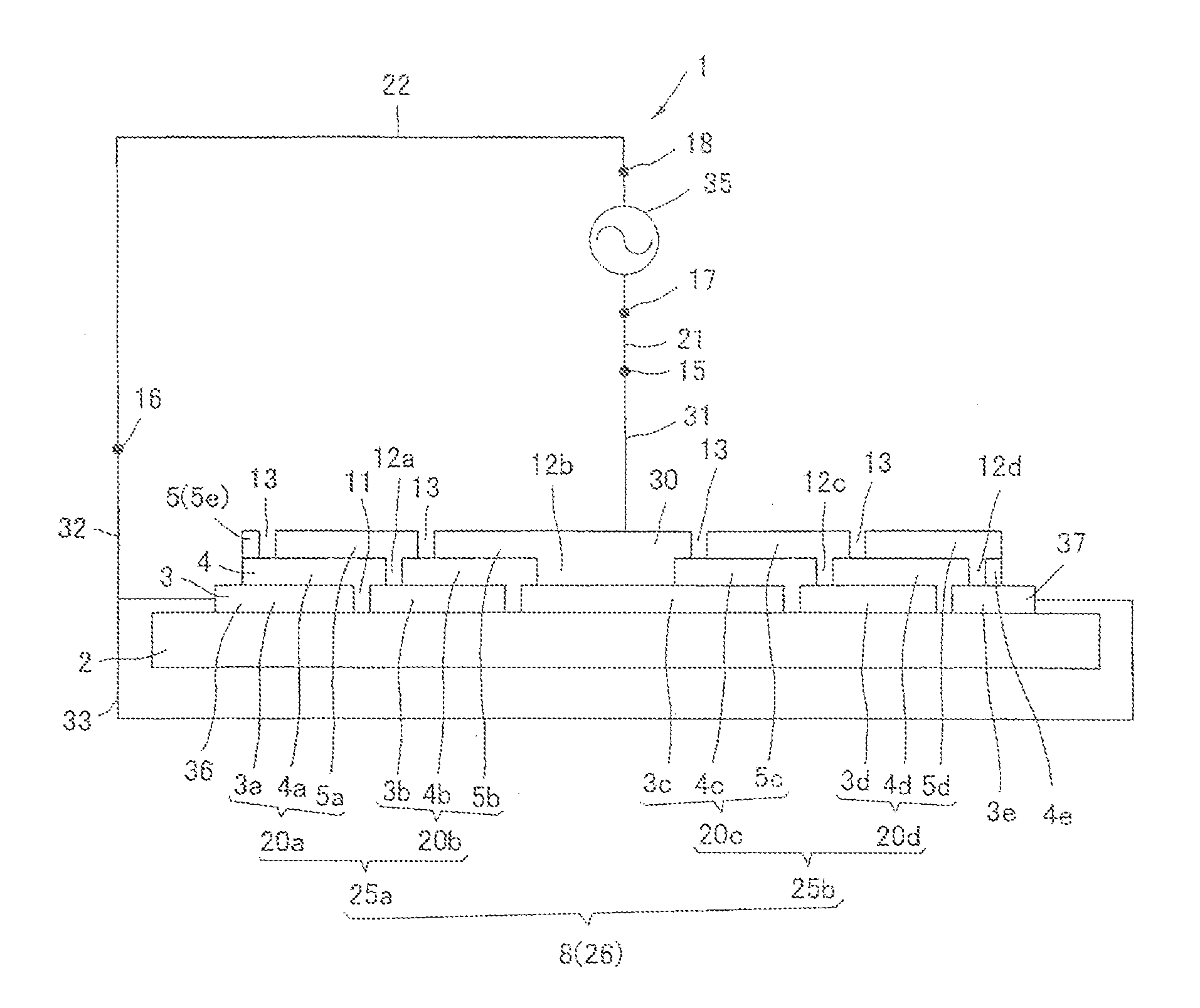
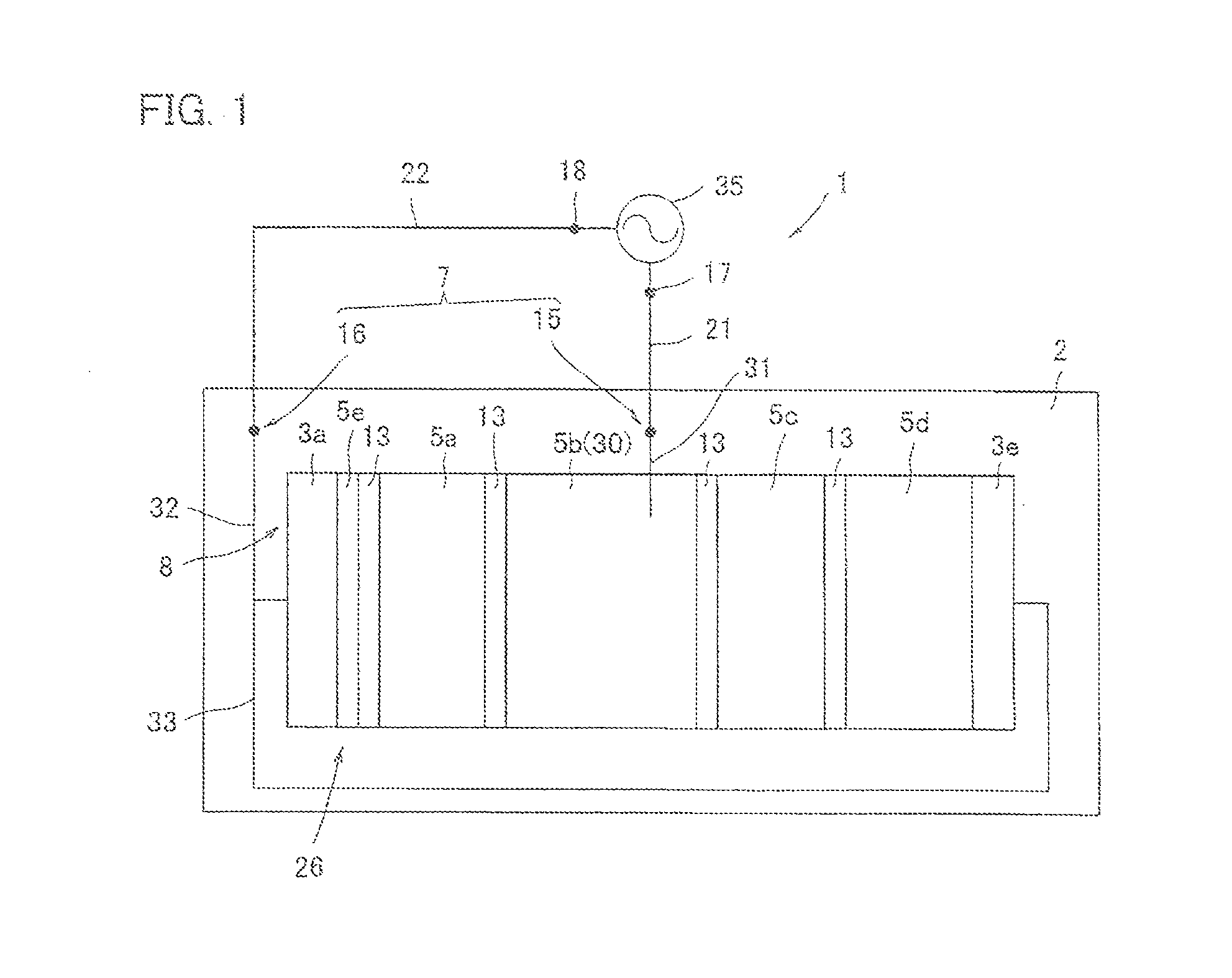
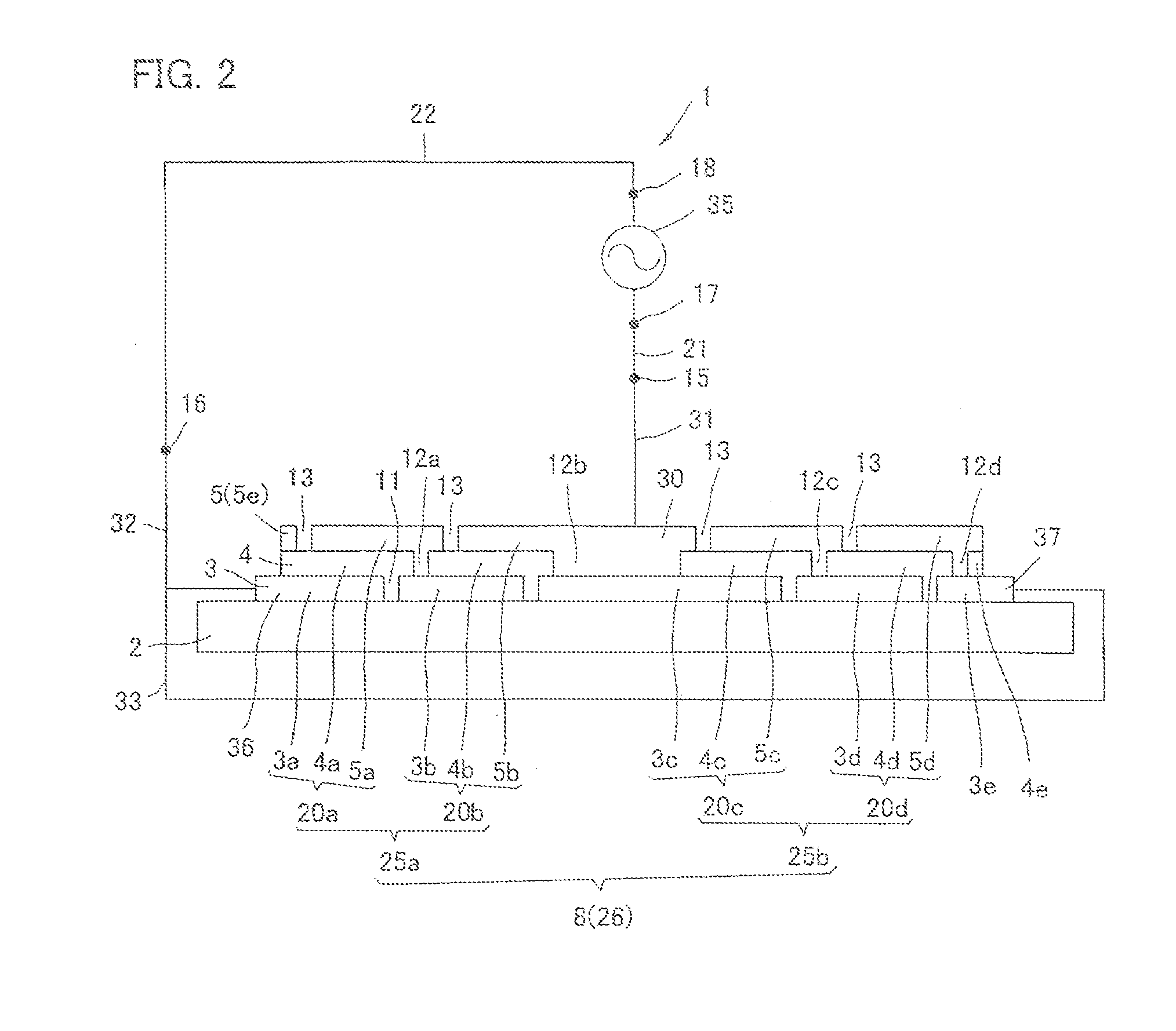
[0056]An organic EL device 1 shown in FIGS. 1 and 2 is constituted in such a manner that a power feeding part 7 and an organic-EL-element forming part 8 formed on a glass substrate (base material) 2.

The organic-EL-element forming part 8 is, as shown in FIG. 2, a part where a front electrode layer 3, which is a first electrode layer (anode), an organic emission layer 4, and a back electrode layer 5, which is a second electrode layer (cathode), are laminated in order.

The front electrode layer 3 is constituted by a known transparent conductive film such as ITO (Indium oxide) or ZnO (Zinc oxide). The front electrode layer 3 has a plurality of fir...


PUM


Abstract

The present invention aims at providing an organic EL device that emits light by an alternating current, has a simple structure and provides little increase of production processes, while downsizing an overall configuration and a simplifying a method for producing said organic EL device. The organic EL device includes a power feeding part and an organic-EL-element forming part. The organic-EL-element forming part includes a plurality of unit EL elements formed on a substrate. There is provided a plurality of series-connected parts each formed by a plurality of the unit EL elements that are electrically connected in series in a forward direction. A plurality of the series-connected parts are electrically connected to the power feeding part in parallel. The series-connected parts that are connected in parallel include a series-connected part that is connected to the power feeding part so as to have a reverse polarity.

Description

TECHNICAL FIELD[0001]The present invention relates to an organic EL device and a method for producing an organic EL device. Specifically, the present invention relates to an organic EL device that uses an alternating current to emit light and achieves a simplification of said device.BACKGROUND ART[0002]Organic EL (Electro Luminescence) devices are attracting attention as lighting equipment of future generations, and have been much studied. An organic EL device is formed by laminating organic EL elements composed of substances such as organic compounds on a substrate such as a glass substrate or a transparent resin film. An organic EL element is a light emitting element that has an organic emission layer provided between an anode and a cathode. An organic emission layer is composed of layers such as a hole injection layer, a hole transport layer, an emission layer, an electron transport layer, and an electron injection layer.[0003]An organic EL device is intrinsically a device that e...

Claims


Application Information

Patent Timeline
IPC IPC(8): H01L51/50H05B44/00
CPCH01L51/5012H05B45/42H10K59/84H10K59/86H10K71/841H10K50/11
Inventor NISHIKAWA, AKIRAAYUKAWA, SHIGERUYAMAGISHI, HIDEO
Owner KANEKA CORP
Learn More