Fixing apparatus and image forming apparatus including the same

a technology of fixing apparatus and fixing plate, which is applied in the direction of electrographic process apparatus, instruments, optics, etc., can solve the problems of overheating of the heated member, overheating of the belt and the melting point of the heated plate, and the temperature of a portion, so as to improve the durability secure the life of the external heating pla

Inactive Publication Date: 2007-10-25
SHARP KK
View PDF2 Cites 21 Cited by
  • Summary
  • Abstract
  • Description
  • Claims
  • Application Information

AI Technical Summary

Benefits of technology

[0016]The present invention was made to solve the above problems, and an object of the present invention is to improve the durability of an external heating belt and adequately secure the life of the external heating belt, in a fixing apparatus including the regulating member which regulates the position of the external heating belt in a rotation axis direction.

Problems solved by technology

If the fixing apparatus is stopped suddenly in this state, the temperature of a portion of the belt which portion contacts the support roller including therein the heat source becomes high, and may exceed the melting points of the belt and the heated member.
In such a case, heat deterioration occurs on the surfaces of the belt and the heated member, smooth rotation of the belt and heat conduction to the heated member deteriorate, and uneven fixation occurs on a fixed image.

Method used


Image

  • Fixing apparatus and image forming apparatus including the same
  • Fixing apparatus and image forming apparatus including the same
  • Fixing apparatus and image forming apparatus including the same

Examples


embodiment 1

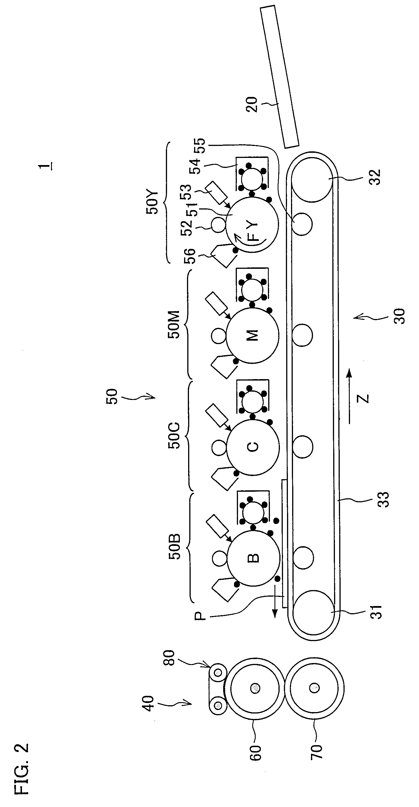
[0031]One embodiment of the present invention is described as follows. First, with reference to FIG. 2, an image forming apparatus 1 including a fixing apparatus of the present embodiment is described. FIG. 2 is a schematic illustrating an internal arrangement of the image forming apparatus 1. The image forming apparatus 1 is a dry electrophotographic color image forming apparatus and serves as a printer which forms a color image or a monochrome image onto a sheet (recording material, transfer medium, recording sheet) P in accordance with image data sent from each terminal device connected via a network or image data scanned by a scanner.

[0032]The image forming apparatus 1 is a dry electrophotographic and quadruple tandem type color printer and includes a visible image transfer section 50, a sheet transport section 30, a fixing apparatus 40, a sheet feeding tray 20.

[0033]The visible image transfer section 50 includes a yellow image transfer section 50Y, a magenta image transfer sect...

example 1

[0110]The durability of the belt in the fixing apparatus 40 explained in Embodiment 1 was measured.

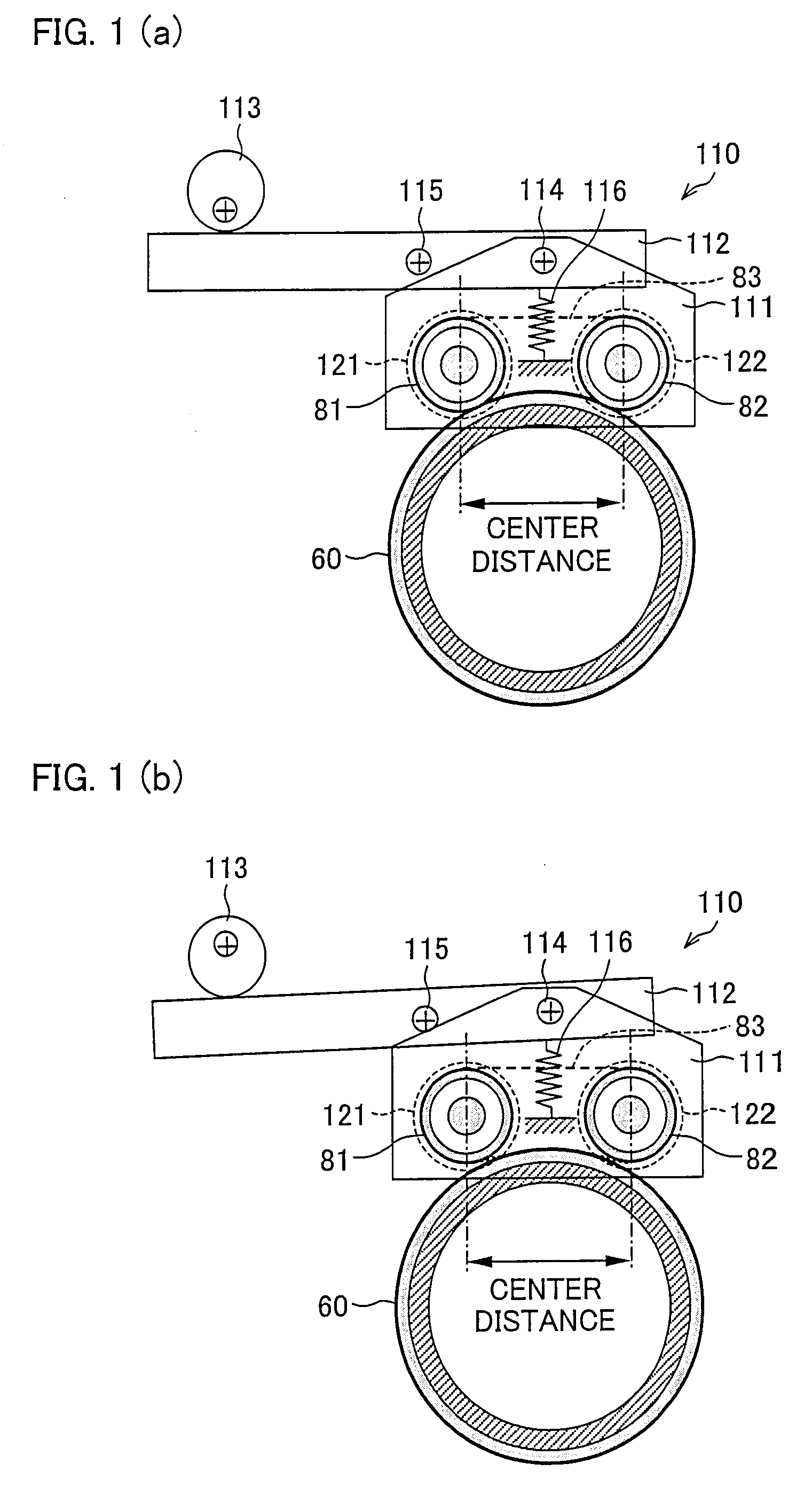
[0111]In the present Example, as the base material of the endless belt 83 formed by stacking the releasing layer, having a thickness of 20 μm and made of PTFE and PFA, on the outermost surface of the base material having a thickness of 100 μm, used was a base material formed by dispersing 10 parts by weight of graphite in polyimide (Product Name: Upilex S, produced by UBE INDUSTRIES, LTD.) having a tensile strength of 500 MPa. Moreover, the belt regulating members 121 and 122 were rotatable in the same rotational direction as the endless belt 83, and movable in the axis direction of the support rollers 81 and 82 independently from the support rollers 81 and 82.

[0112]Since the sheets were sequentially output at an output rate of 70 sheets per minute (horizontal transport of A4 sheets) at a low-temperature environment (7° C.) with a basis weight of 105 g / m2, the temperature of the fixing...

embodiment 2

[0116]Another embodiment of the present invention is described as follows. Note that, for convenience in description, the same reference numerals as Embodiment 1 are given to members having the same functions as those of the members described in Embodiment 1, and descriptions thereof are omitted.

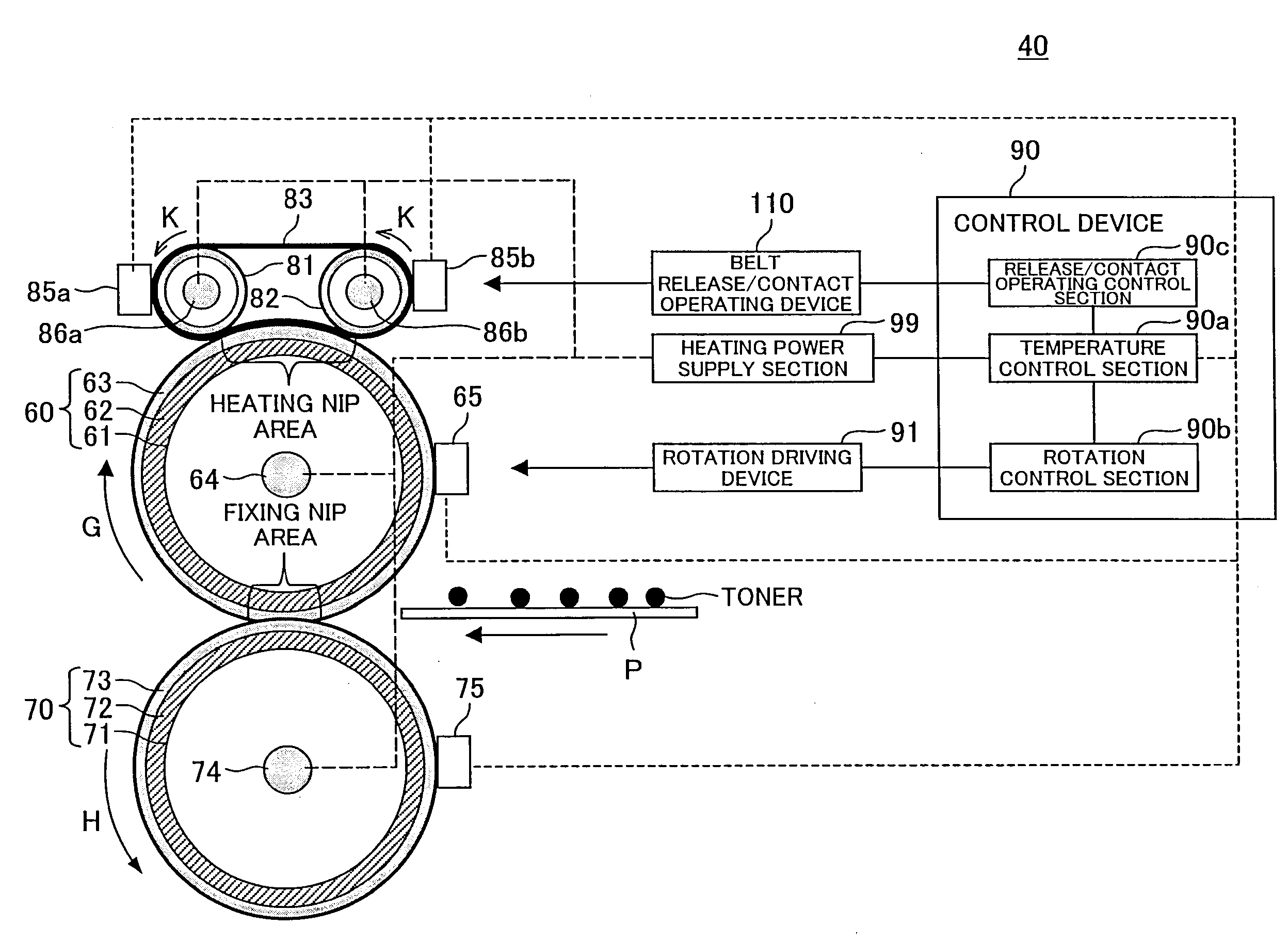
[0117]The present embodiment is different from Embodiment 1 in that there is not provided an external heating device 80 for heating the peripheral surface of the fixing roller 60 and there is provided an external heating device for heating the peripheral surface of the pressing roller 70. That is, the fixing apparatus according to the present embodiment includes the external heating device for coming into contact with the peripheral surface of the pressing roller 70, which is in contact with the rear surface (surface having no unfixed image thereon) of the sheet P, at the fixing nip section, so as to heat the peripheral surface of the pressing roller 70.

[0118]Each of FIGS. 6(a) and 6(b) illu...


PUM


Abstract

In a fixing apparatus including a regulating member which regulates the position of an external heating belt in a rotation axis direction, the external heating belt includes a base material made of polyimide having a tensile strength of 300 MPa or more and a thickness of 50 μm to 200 μm, and a releasing layer. In the base material, 5 to 25 parts by weight of graphite is dispersed in 100 parts by weight of polyimide. With this, it is possible to improve the durability of the external heating belt and adequately secure the life of the external heating belt.

Description

[0001]This Nonprovisional application claims priority under 35 U.S.C. § 119(a) on Patent Application No. 118512 / 2006 filed in Japan on Apr. 21, 2006, the entire contents of which are hereby incorporated by reference.FIELD OF THE INVENTION[0002]The present invention relates to (i) a fixing apparatus used in an electrophotographic image forming apparatus and (ii) an electrophotographic image forming apparatus using the fixing apparatus.BACKGROUND OF THE INVENTION[0003]Conventionally, as a fixing apparatus used in an electrophotographic image forming apparatus such as a copying machine, a printer, and the like, the following type of fixing apparatus has generally been used. Specifically, this conventionally-used fixing apparatus (heat roller fixing apparatus) includes a fixing roller and a pressing roller which are pressed against each other, wherein heating means constituted of a halogen lamp (halogen heater) disposed in the fixing roller or halogen lamps (halogen heaters) disposed in...

Claims


Application Information

Patent Timeline
Patent Type & Authority Applications(United States)
IPC IPC(8): G03G15/20
CPCG03G15/2064G03G2215/2019G03G2215/2016
Inventor ASAKURA, KENJIYAMAJI, HIROYUKIKAGAWA, TOSHIAKI
Owner SHARP KK
Why Eureka
Try Eureka