
Pressurized medical device

a medical device and pressurized technology, applied in the field of pressurized medical devices, can solve the problems of reducing the residence time of blood supplied to the lower limb, tissue breakdown, and many patients' unsightly, uncomfortable, hot or painful,

Active Publication Date: 2007-10-25
SWELLING SOLUTIONS
View PDF9 Cites 37 Cited by
  • Summary
  • Abstract
  • Description
  • Claims
  • Application Information

AI Technical Summary

Benefits of technology

[0017] The control system is, preferably, arranged to control the fluid flow to reduce the exerted pressure to substantially zero if an element pressure sensor detects a pressure exceeding a first predefined amount. Preferably, the control system is arranged to control the fluid flow to reduce the exerted pressure to substantially zero if the reference pressure sensor detects a pressure exceeding a second predefined amount. Preferably, the second predefined amount is greater than the first predefined amount. The contro...

Problems solved by technology

This in turn reduces the residence time for blood supplied to the lower limb and the severity of ischaemic episodes within the limb that can result in tissue breakdown.
They can work loose, the pressure generated by the bandage on the limb is not measured and depends on the level of skill of the health care professional applying the bandage, the level of compression is also affected by the circumference of the limb, the bandage cannot be removed and reapplied by the patient, for instance for bathing, and many patients find them unsightly, uncomfortable, hot or painful.
They are difficult to apply as the narrow ankle part has to be pulled over the heel, compliance with treatment is difficult to monitor as the patient may be able to remove and replace the stocking themselves and patients can find them uncomfortable.
As venous leg ulcers are most usually treated at home or in the community and the known compression devices are large, heavy and require professional supervision, their adoption for such treatment has not been widespread.
The known devices used previously apply pressure to the limb through a thick cuff or cuffs which affect patient mobility and are aesthetically unacceptable to many patients.
The pump which produces the compression is large and heavy and can supply fluid to the cuffs through many pipes.
These characteristics make the known devices unsuitable for home use.

Method used


Image

  • Pressurized medical device
  • Pressurized medical device
  • Pressurized medical device

Examples


Embodiment Construction

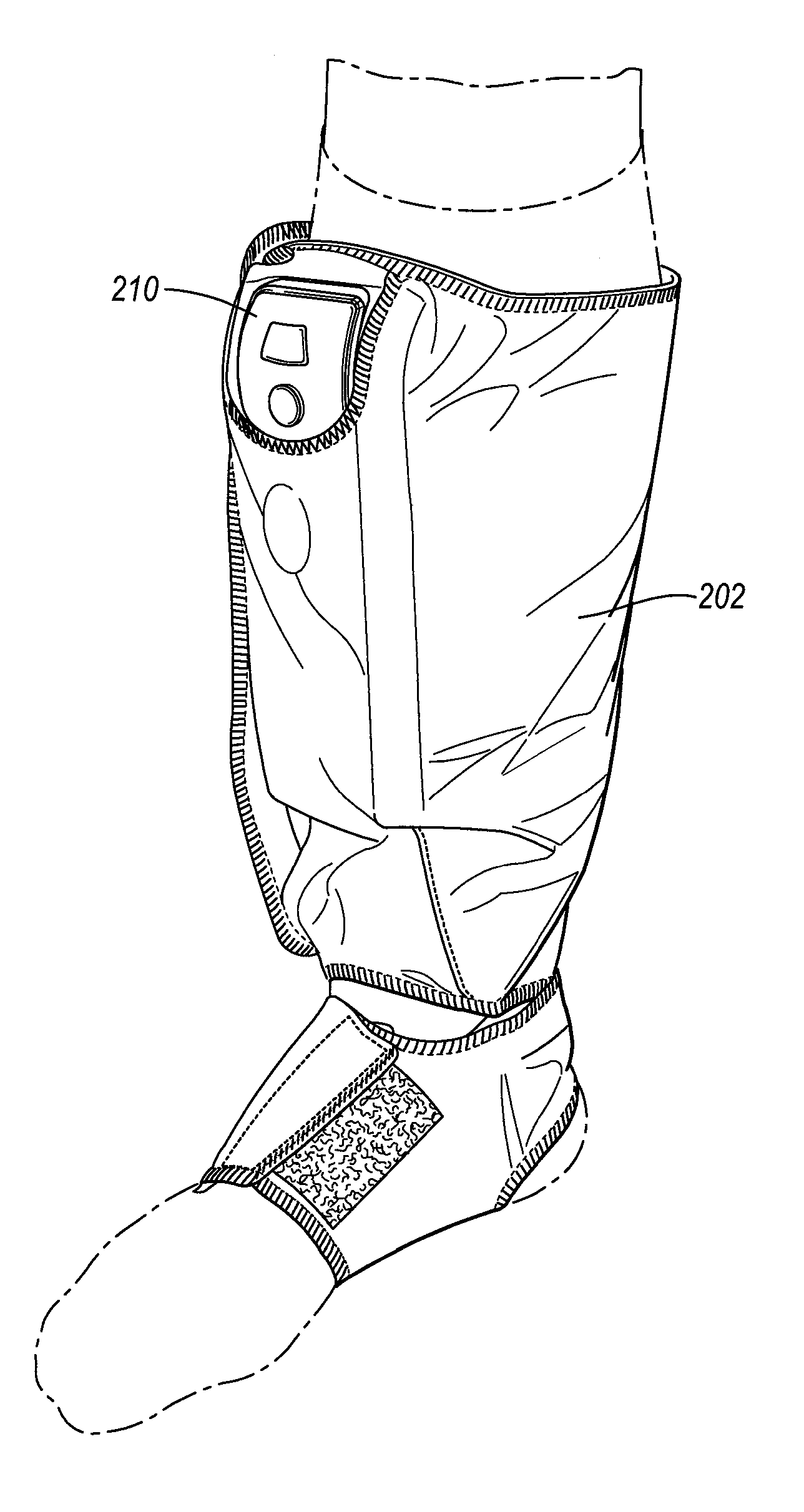
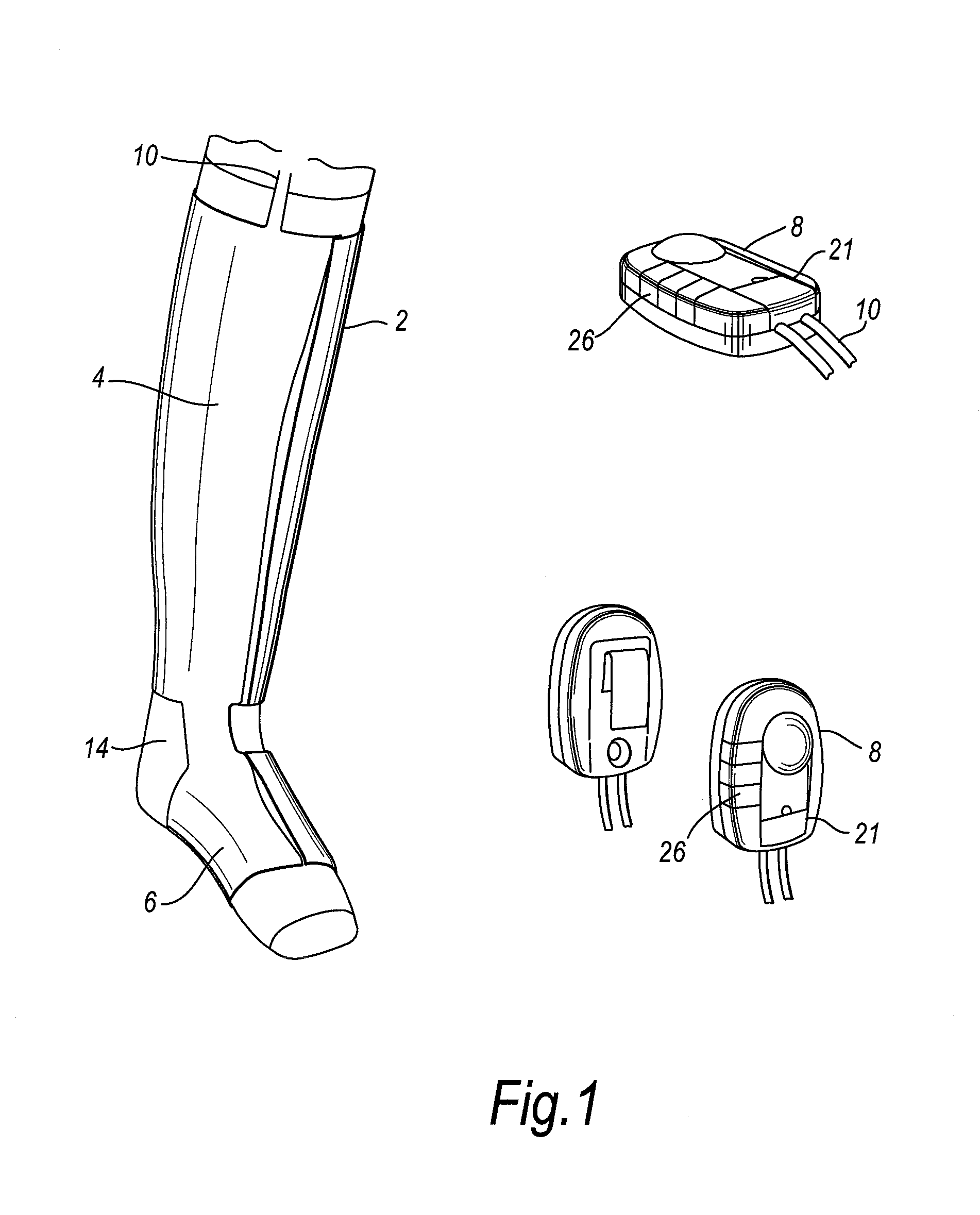
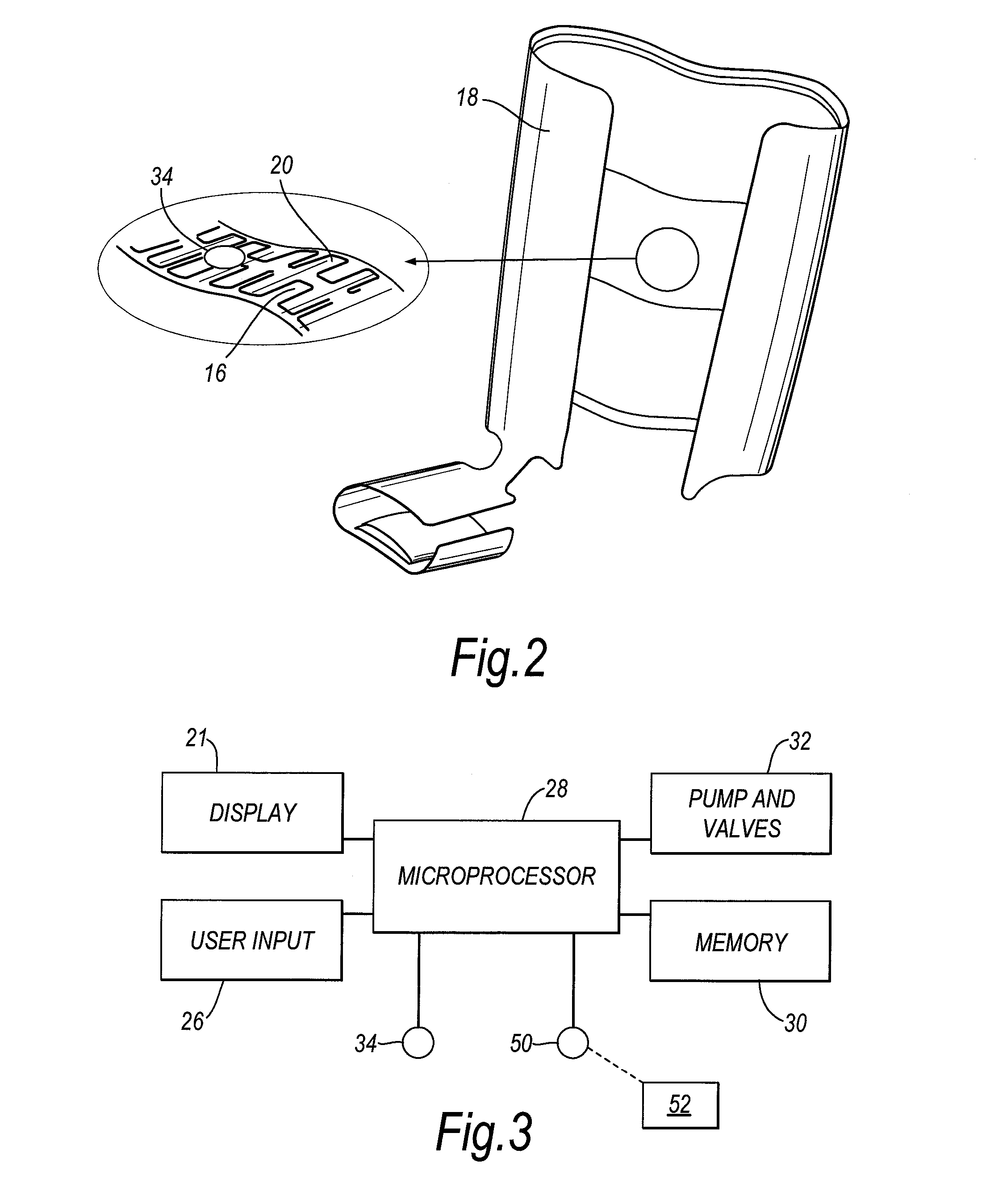
[0026] In FIG. 1 a compression device according to a first embodiment of the invention is shown on the leg of a patient in a standing position. The device comprises a sleeve 2 having a leg cuff 4 connected to a foot cuff 6. The device also comprises a control system housed within a controller unit 8. The sleeve 2 is connected to the controller unit 8 by a fluid connector in the form of a conduit 10. The controller unit 8 is a small, hand held unit that may be clipped to the sleeve 2 or to the waistband of the patient's trousers or skirt. The controller unit 8 is battery powered, by a rechargeable battery. The device also comprises an understocking 14 worn between the patient's leg and the sleeve 2. The understocking 14 is present to absorb any moisture from the patient's leg but does not apply compression. The sleeve 2 has an inner surface 16 and an outer surface 18 composed of a durable flexible material that can be sponged clean and is divided into a plurality of minicells 20 best...


PUM


Abstract

A pressurized medical device comprising an inflatable element arranged to contact a part of a patient; a fluid connector attached to the element and arranged to deliver fluid to the element; a control system arranged to control flow of fluid in the device; a first element pressure sensor arranged to measure the pressure exerted by the element on the part of the patient; and detection means arranged to detect malfunctioning of the first element pressure sensor.

Description

[0001] This invention relates to pressurized medical devices. For example, the invention relates to a compression device for the limb and, particularly, to a device for use on the leg. For example, the device may be used for compression therapy used in the treatment of venous leg ulcers. BACKGROUND OF THE INVENTION [0002] Various compression devices are known for applying compressive pressure to a patient's limb. These types of devices are used to assist mainly in the prevention of deep vein thrombosis (DVT), vascular disorders and the reduction of oedema. U.S. Pat. No. 6,786,879 and U.S. Patent Publication No. 2004 / 0111048 disclose such devices. [0003] Compression therapy is used in the treatment of venous leg ulcers. The treatment relies on the compression achieving a reduction in oedema and improved return of blood via the venous system. This in turn reduces the residence time for blood supplied to the lower limb and the severity of ischaemic episodes within the limb that can res...

Claims


Application Information

Patent Timeline
IPC IPC(8): A61F5/04
CPCA61H2205/10A61H2205/12A61H9/0078A61H2201/0134A61H2201/5002A61H2201/5007A61H2209/00A61H2201/0119A61H2201/1628A61H2201/1635A61H2201/164A61H2201/165A61H2201/0146
Inventor BONNEFIN, WAYNE LEEROWLEY, DUNCAN JOHNLANDAHL, HENRIKLARSSON, ROLANDFERNANDEZ, ARSENIO
Owner SWELLING SOLUTIONS
Learn More