Supercharge Your Innovation With Domain-Expert AI Agents!

Valve mechanism and flow channel substrate

a valve mechanism and flow channel substrate technology, applied in the field of valve mechanisms, can solve the problems of increasing cost and general complexity of the flow channel substrate structure, and achieve the effect of high integration and good respons

Inactive Publication Date: 2007-11-01
SHIMADZU CORP
View PDF9 Cites 6 Cited by
  • Summary
  • Abstract
  • Description
  • Claims
  • Application Information

AI Technical Summary

Benefits of technology

The present invention provides an embedded valve mechanism that can be directly controlled without adding complexity to the structure of a flow channel substrate. The valve mechanism comprises a valve chamber and a valve body, which can be opened or closed by a magnet. The valve body is driven by an electromagnetic force, making the response good and allowing for easy integration into the flow channel substrate. The flow channel substrate integrates multiple flow channels and the valve mechanism, providing multiple functions and high level of integration.

Problems solved by technology

However, not only it is difficult to embed the valve mechanism in the flow channel substrate, the structure of the flow channel substrate itself will generally become complicated.
If the structure of the flow channel substrate becomes complicated, the number of procedures for fabricating the flow channel substrate must increase, which lead to the increase of cost.

Method used


Image

  • Valve mechanism and flow channel substrate
  • Valve mechanism and flow channel substrate
  • Valve mechanism and flow channel substrate

Examples


Embodiment Construction

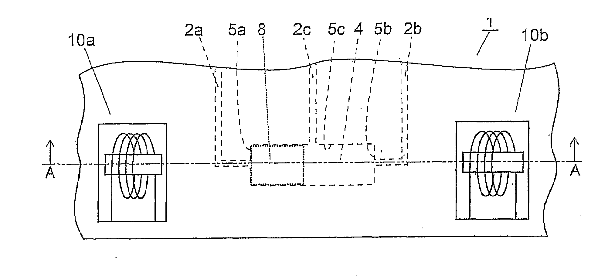
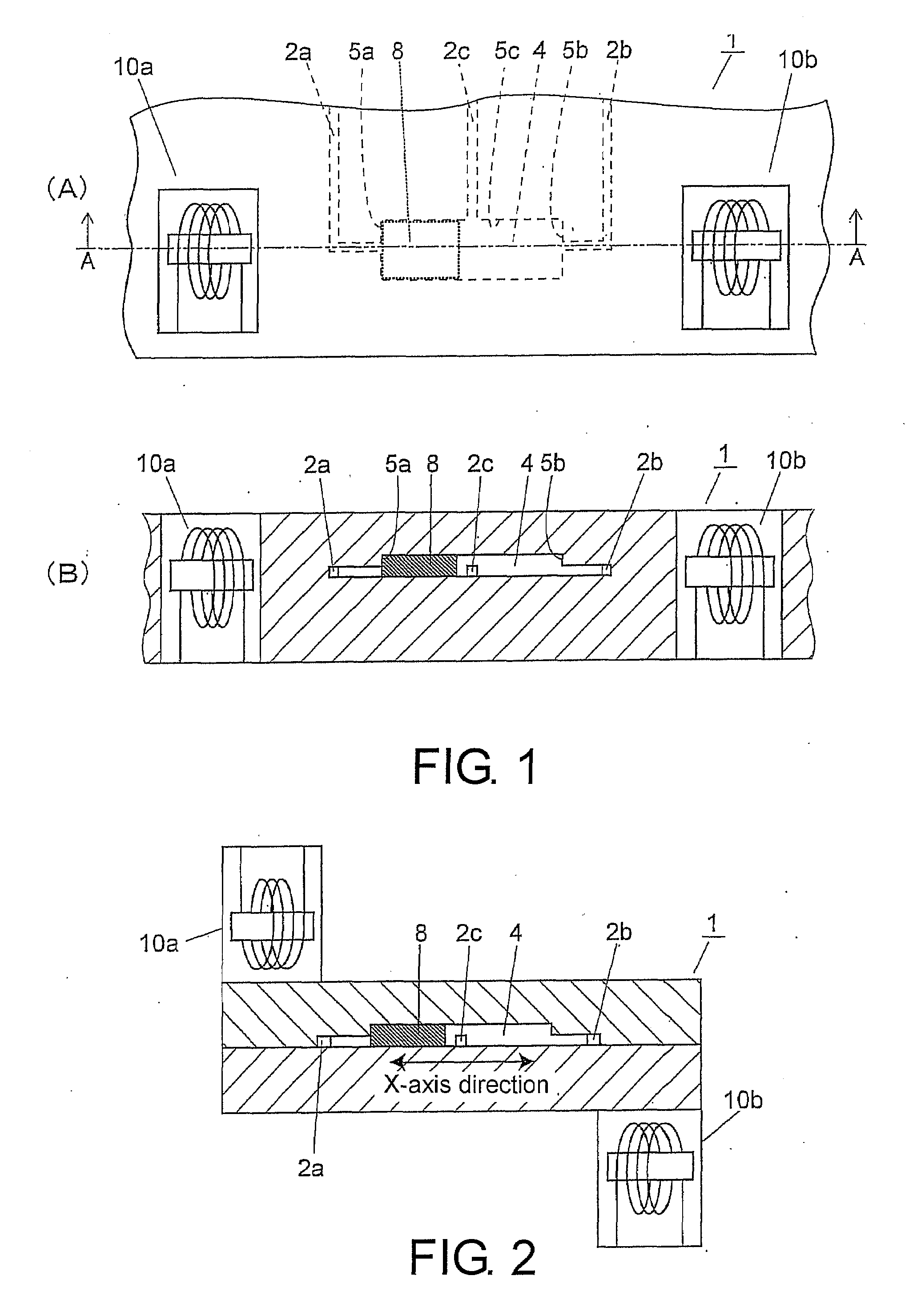
[0021]FIGS. 1(A) and (B) are schematic views of the valve mechanism in the flow channel substrate according to an embodiment, in which FIG. 1(A) is a plan view, and FIG. 1(B) is a sectional view taken along line A-A of FIG. 1(A).

[0022]A rectangular space, i.e., a valve chamber 4, is formed in a flow channel substrate 1. Flow channels 2a, 2b, and 2c are connected to the valve chamber 4 from different directions. The flow channels 2a and 2b are connected respectively to a first surface 5a and a second surface 5b, opposite to the first surface 5a, of the valve chamber 4. The flow channel 2c is connected to a third surface 5c different from the first surface 5a and the second surface 5b.

[0023]A valve body 8 is accommodated in the valve chamber 4. The valve body 8 slides between the first surface 5a and the second surface 5b in the valve chamber 4. The valve body 8 is formed by a magnetic material such as Fe, Cu, or Ni, or resin, and a magnet or magnetic particles are buried in the valv...


PUM


Abstract

A valve mechanism is provided, which can be embedded in a flow channel substrate without adding complexity of structure of the flow channel substrate. A rectangular space, i.e. a valve chamber, is formed in a flow channel substrate (1). Flow channels (2a, 2b, 2c) are connected to the valve chamber from different directions. The flow channels (2a, 2b) are connected respectively to a first surface and a second surface, opposite to the first surface, of the valve chamber. The flow channel (2c) is connected to a third surface different from the first and the second surfaces. A valve body 8 is accommodated in the valve chamber 4. The valve body slides between the first and the second surfaces in the valve chamber. On the sides of the first and the second surfaces outside the valve chamber, electromagnets are buried in the flow channel substrate (1) to sandwich the valve chamber.

Description

CROSS-REFERENCE TO RELATED APPLICATION[0001]This application claims the priority benefit of Japan application serial no. 2006-127318, filed May 1, 2006. All disclosure of the Japan application is incorporated herein by reference.BACKGROUND OF THE INVENTION[0002]1. Field of the Invention[0003]The present invention relates to a valve mechanism for switching on or off a fluid in a flow channel, or selectively switching the connected flow channel. More particularly, the present invention relates to a valve mechanism embedded in a flow channel substrate such as a microchip or a capillary plate, and a flow channel substrate with the valve mechanism embedded therein.[0004]2. Description of Related Art[0005]In order to realize a multifunction of a substrate with microchannels formed therein so as to achieve a high level of integration, a valve mechanism for controlling the fluid flowing in the flow channels is required to be embedded in the flow channel substrate itself. However, not only i...

Claims


Application Information

Patent Timeline
Patent Type & Authority Applications(United States)
IPC IPC(8): F16K11/07
CPCF15C5/00F16K99/0001F16K99/0046F16K99/0026F16K99/0011Y10T137/86879F16K31/06H01F7/16
Inventor KAJI, TORU
Owner SHIMADZU CORP
Features
  • R&D
  • Intellectual Property
  • Life Sciences
  • Materials
  • Tech Scout
  • Unparalleled Data Quality
  • Higher Quality Content
  • 60% Fewer Hallucinations
Learn More