Pulling tool

a technology of pulling tool and crowbar, which is applied in the field of pulling tool, can solve the problems of time-consuming, difficult to remove the portion of the article being replaced that is covered by the other article or structure, and difficult to remove the portion of the shingles under the flashing that is difficult to remove, so as to achieve the effect of convenient removal

Inactive Publication Date: 2007-11-01
HARPELL WILLIAM
View PDF9 Cites 9 Cited by
  • Summary
  • Abstract
  • Description
  • Claims
  • Application Information

AI Technical Summary

Benefits of technology

[0005] It is the purpose of the present invention to provide a tool that makes it easier to remo

Problems solved by technology

It is often difficult to remove all of the article, such as a shingle or carpet, when replacing it.
Often, the article is installed partly under another article or structure that is not being replaced, and it is difficult to remove that portion of the article being replaced that is covered by the othe

Method used


Image

  • Pulling tool
  • Pulling tool
  • Pulling tool

Examples


Embodiment Construction

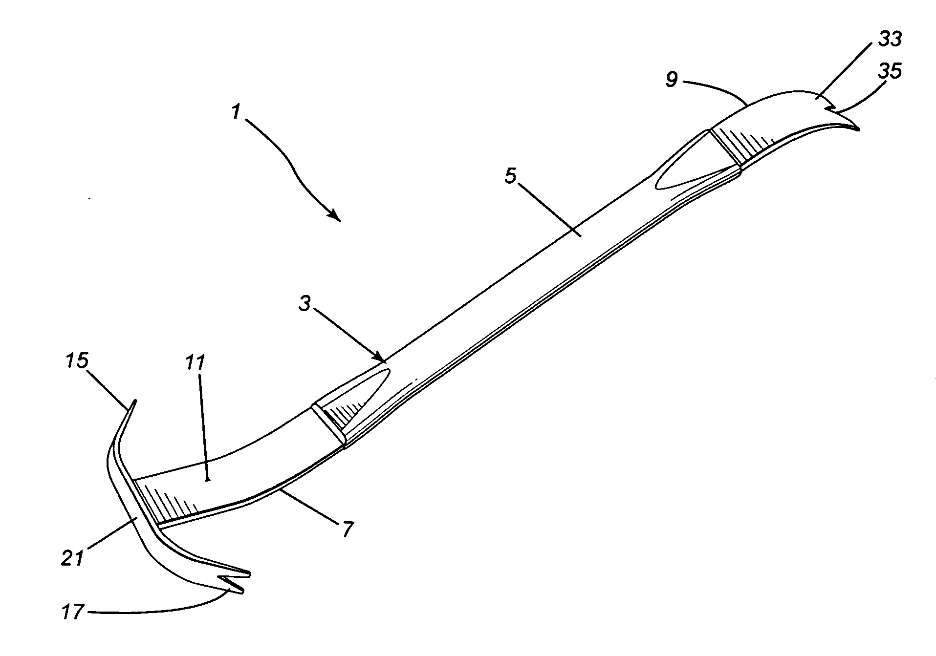
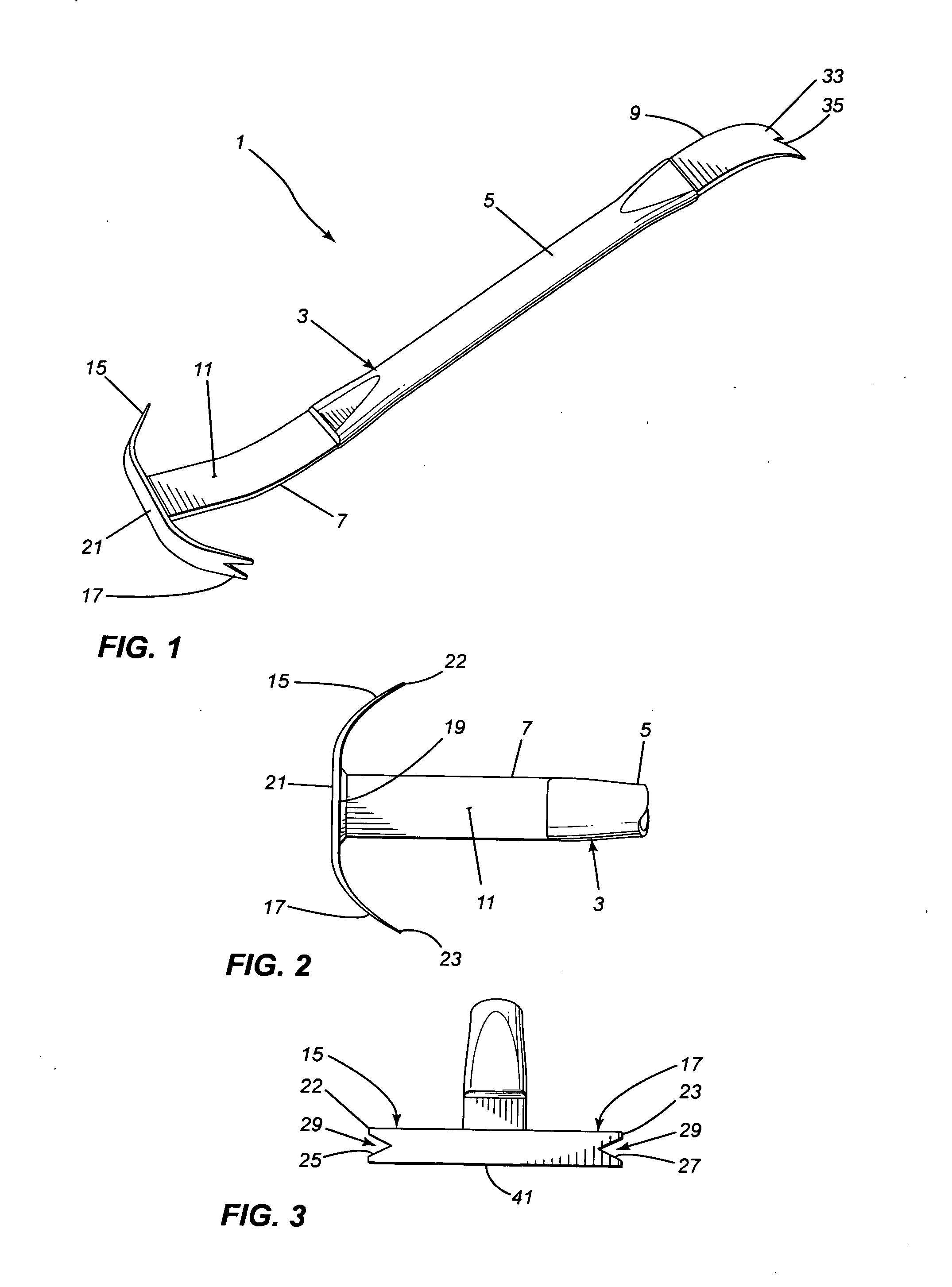
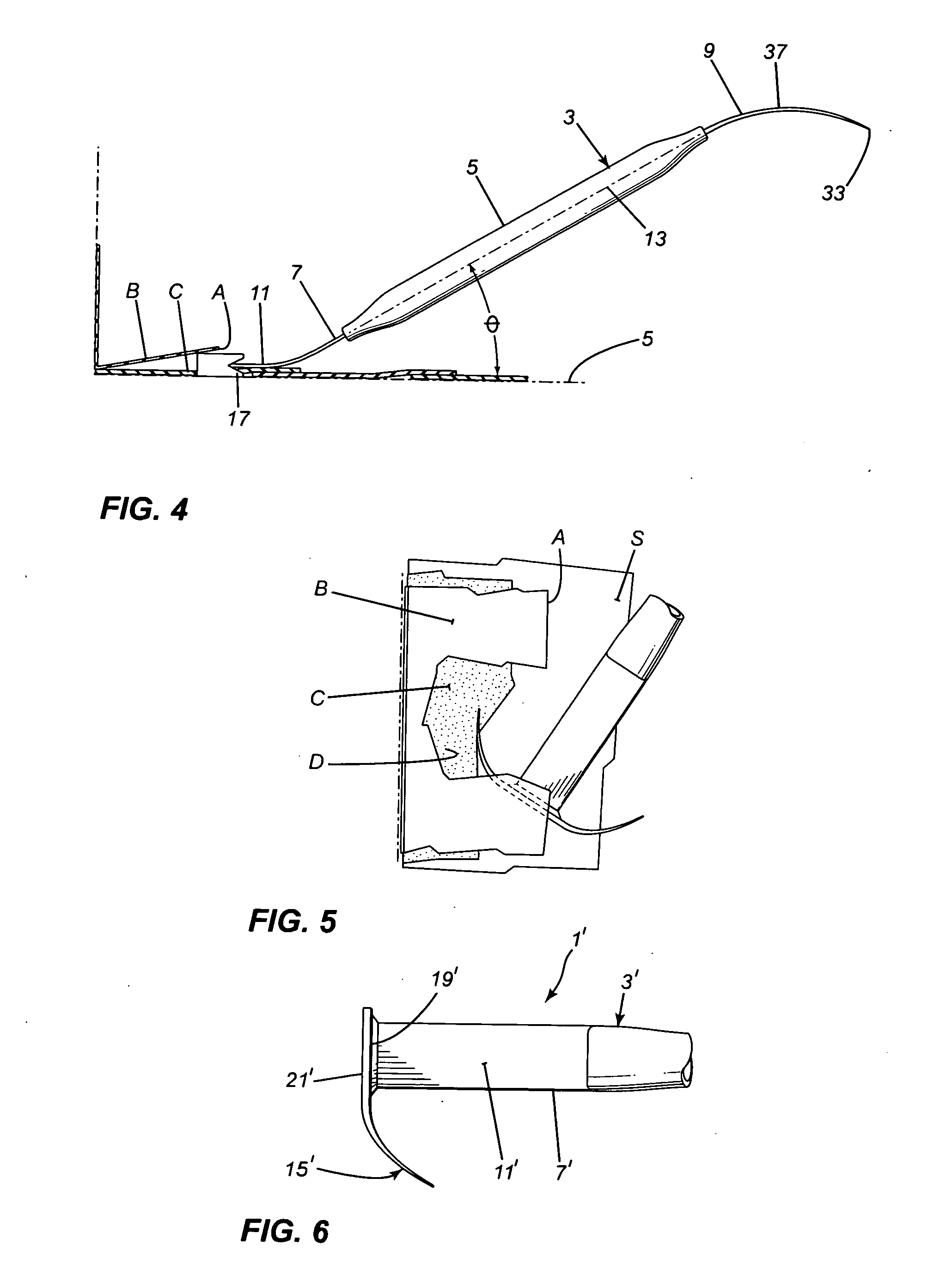
[0017] The tool 1, as shown in FIGS. 1 to 3, has a handle 3 with a main tubular body portion 5 and a flat end portion 7, 9 at each end of the body portion 5. The main body portion 5 is straight and two to three times the length of the flat end portions 7, 9. When the main body portion 5 of the handle 3 is horizontal, one flat end portion 7 is bent upwardly and terminates in a straight end section 11. The other flat end portion 9 is bent downwardly in a direction opposite to the direction in which the first end portion 7 is bent from the main body portion 5. The straight end section 11 extends at a shallow angle Ø to the longitudinal axis 13 of the main body portion 5 of the handle as shown in FIG. 4. The angle Ø is about twenty to twenty five degrees but can range from around fifteen degrees to around thirty degrees.

[0018] A double claw 15, 17 is provided at the free end 19 of the one flat end portion 7. The two claws 15, 17 are formed by a narrow, thin, elongate claw member 21 ext...


PUM


Abstract

A pulling tool for grabbing and pulling material from underneath structural elements. The tool has a handle, the handle having a main body portion and having one flat end portion bent from one end of the body portion. A thin, narrow, claw member is attached to the free end of the one end portion and extends across and past both sides of the one end portion to form a claw on each side of the handle at one end of the handle. Each claw is tapered to a straight end edge which edge is transverse to the end portion. Each claw has a narrow v-shaped material receiving slot extending inwardly from the straight end edge to allow the claw to grab the material being removed.

Description

BACKGROUND OF THE INVNETION [0001] 1. Field of the Invention [0002] This invention is directed toward a pulling tool for pulling articles, or portions thereof, out from under constructional elements or other awkward locations. [0003] 2. Description of the Related Art [0004] It is often difficult to remove all of the article, such as a shingle or carpet, when replacing it. Often, the article is installed partly under another article or structure that is not being replaced, and it is difficult to remove that portion of the article being replaced that is covered by the other article or structure. In the case of roof shingles, for example, an edge portion of the shingles to be replaced can be covered with roof flashing that stays in place during shingle replacement. The portion of the shingles under the flashing is difficult, and thus time consuming, to remove. When replacing carpeting, an edge portion of the carpeting is often under baseboard moulding and again it is difficult to remov...

Claims


Application Information

Patent Timeline
IPC IPC(8): B66F13/00
CPCB66F15/00B25C11/00
Inventor HARPELL, WILLIAM
Owner HARPELL WILLIAM
Why Eureka
Try Eureka