Embedded magnet type rotating electric machine

a technology of embedded magnets and rotating electric machines, which is applied in the direction of dynamo-electric machines, magnetic circuit rotating parts, and shape/form/construction of magnetic circuits, etc., can solve the problems of low motor efficiency and small magnetic flux of the rotor with respect to the stator, and achieve the effect of reducing the flux of leakag

Active Publication Date: 2007-11-01
DENSO CORP
View PDF10 Cites 94 Cited by
  • Summary
  • Abstract
  • Description
  • Claims
  • Application Information

AI Technical Summary

Benefits of technology

[0005] An objective of the present invention is to provide an embedded magnet type rotating electric machine which can reduce a leakage flux.

Problems solved by technology

As a result, an effective magnetic flux of the rotor with respect to the stator is small, and a motor efficiency is low.

Method used


Image

  • Embedded magnet type rotating electric machine
  • Embedded magnet type rotating electric machine
  • Embedded magnet type rotating electric machine

Examples


first embodiment

[0047] The first embodiment mentioned above has the following advantages.

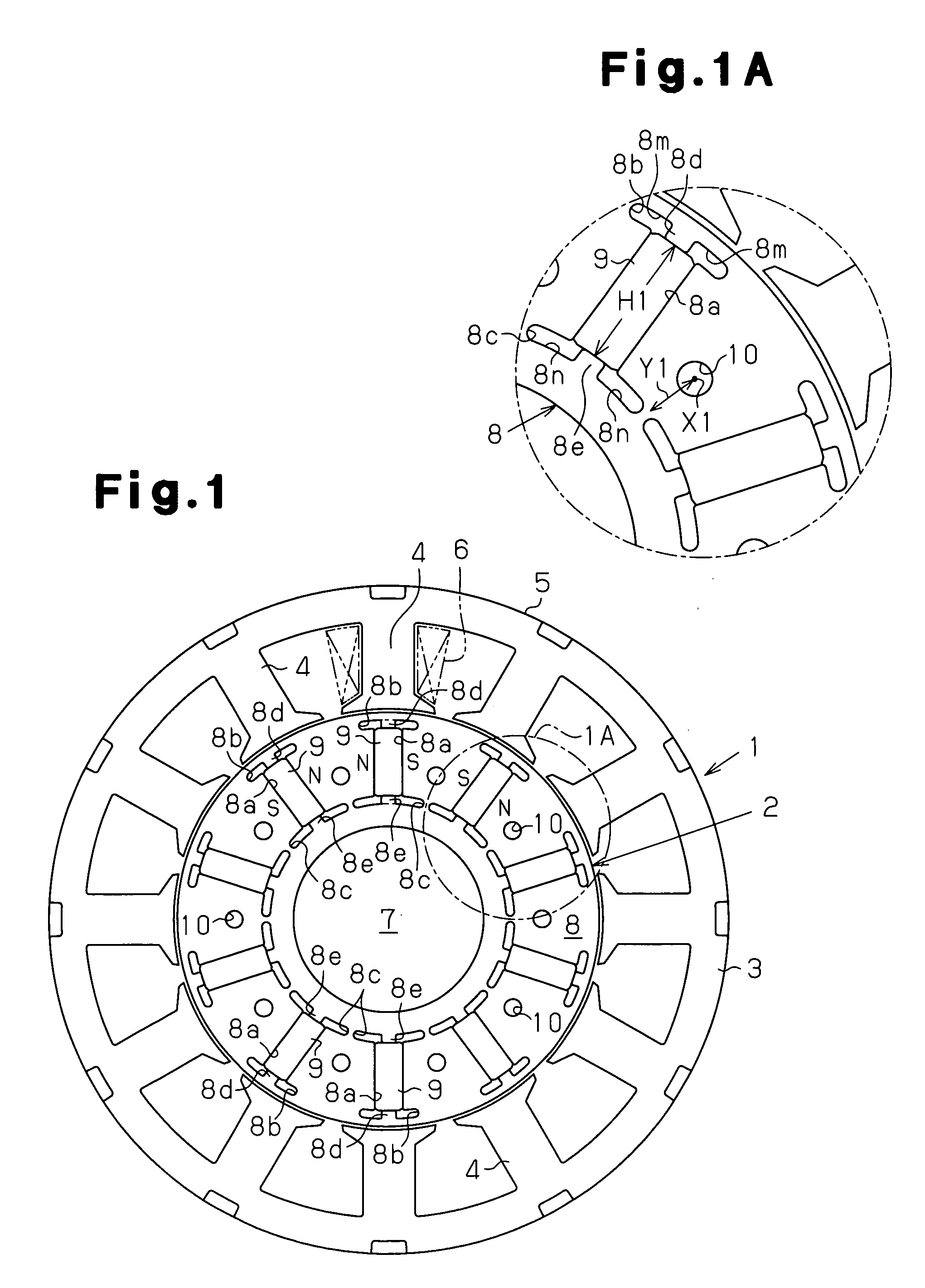
[0048] (1) The rotor core 8 has the first circumferential extension portion 8b positioned in the radially outer end of each of the accommodating holes 8a, and the second circumferential extension portion 8c positioned in the radially inner end of each of the accommodating holes 8a. The dimension in the circumferential direction of each of the circumferential extension portions 8b and 8c is larger than the dimension in the circumferential direction of each of the magnets 9. Each of the circumferential extension portions 8b and 8c extends outward in the circumferential direction with respect to each of the magnets 9. Accordingly, a magnetic resistance of the rotor core 8 is increased. It is possible to reduce a leakage flux directly directed to the S pole of the magnet 9 from the N pole of the magnet 9.

[0049] The rotor core 8 has a plurality of first radial regulating portions 8d respectively brought into contac...

second embodiment

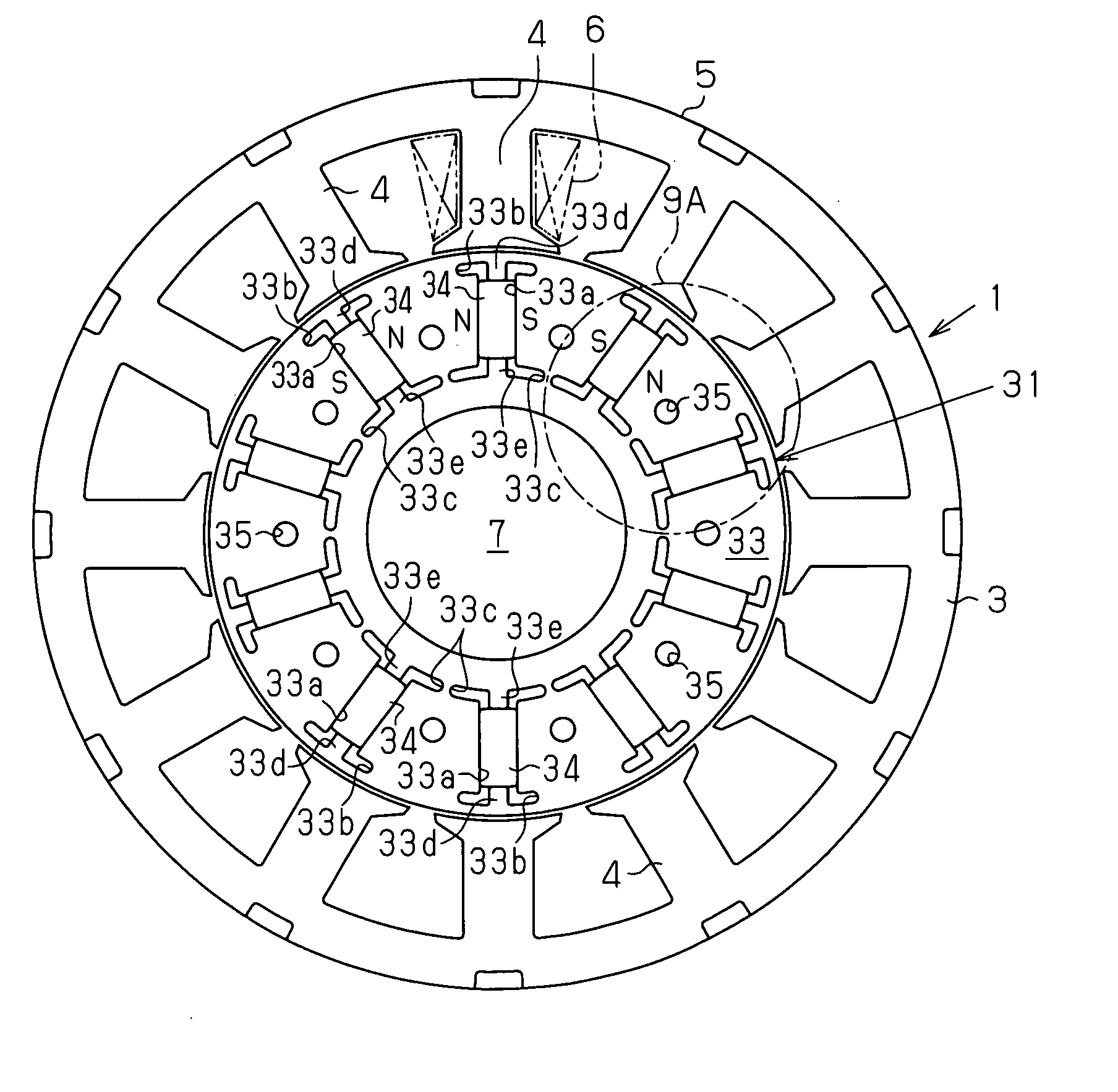
[0064] As shown in FIG. 9, a rotor core 33 in a rotor 31 in accordance with a second embodiment has a first radial regulating portion 33d which is brought into contact with a radially outer end of each of magnets 34, and a second radial regulating portion 33e which is brought into contact with a radially inner end of each of the magnets 34. The radial dimension of the first radial regulating portion 33d is larger than a radial dimension of a first circumferential extension portion 33b. The radial dimension of the second radial regulating portion 33e is larger than the radial dimension of a second circumferential extension portion 33c.

[0065] In the second embodiment, each of the radial regulating portions 33d and 33e is formed in such a manner as to extend entirely in the axial direction of the rotor core 33.

[0066] As shown in FIG. 9A, the rotor core 33 has a pair of first extension spaces 33m holding the first radial regulating portion 33d therebetween, in a radially outer end in ...

third embodiment

[0089] A description will be given below of the present invention with reference to FIG. 14.

[0090] As shown in FIG. 14, a rotor core 38 has a pair of first extension spaces 8t holding the first radial regulating portion 8d therebetween, in the radially outer end in each of the accommodating holes 8a. A pair of first extension spaces 8t extend radially outward from both ends in the circumferential direction of the accommodating hole 8a, and reach a portion close to an outer periphery of the rotor core 8. Each of the first extension spaces 8t does not protrude further outward in the circumferential direction with respect to the magnet 9. The dimension in the circumferential direction, that is, the width of each of the first extension space 8m is constant.

[0091] The rotor core 38 has a pair of second extension spaces 8u holding the second radial regulating portion 8e therebetween, in the radially inner end in each of the accommodating holes 8a. A pair of second extension spaces 8u ser...


PUM


Abstract

A plurality of magnets are arranged in accommodating holes each extending in a radial direction. A rotor core is provided with an extension portion in a circumferential direction extending further outward in the circumferential direction with respect to the magnet from at least one of a radially outer end and a radially inner end in the accommodating hole, and a radial regulating portion regulating a movement of the magnet in the radial direction. The radial regulating portion extends in the radial direction so as to correspond to a center in the circumferential direction of the accommodating hole. The dimension in the circumferential direction of a portion of the radial regulating portion that is brought into contact with the magnet is smaller than the dimension in the circumferential direction of the magnet. A cross-sectional area of the radial regulating portion as seen from the radial direction is small, in comparison with the case in which the radial regulating portion extends entirely in the axial direction of the rotor core. Accordingly, it is possible to reduce a leakage flux in a rotating electric machine.

Description

BACKGROUND OF THE INVENTION [0001] The present invention relates to an embedded magnet type rotating electric machine. [0002] A rotor of the embedded magnet type rotating electric machine has a rotor core and a plurality of magnets embedded in the rotor core. The rotor core has a plurality of accommodating holes lined up in a circumferential direction. Each of the accommodating holes passes through the rotor core in an axial direction, and extends in a radial direction. The magnet is arranged in each of the accommodating holes. [0003] Japanese Laid-Open Patent Publication No. 2004-173491 discloses a circumferential extension portion extending further outward in the circumferential direction with respect to an end in the circumferential direction of a magnet from a radially outer end (an outer end in a radial direction) of an accommodating hole. The circumferential extension portion increases a magnetic resistance, thereby reducing a leakage flux directly directed to an S pole of the...

Claims


Application Information

Patent Timeline
Patent Type & Authority Applications(United States)
IPC IPC(8): H02K21/12H02K1/27
CPCH02K1/2773
Inventor NISHIURA, HIDEAKIYOKOYAMA, SEIYATAKEMOTO, YOSHIAKI
Owner DENSO CORP
Why Eureka
Try Eureka