Linear motor

a linear motor and motor shaft technology, applied in the field of linear motors, can solve the problems of increasing the above-described leakage magnetic flux, lowering thrust, and leaking magnetic flux out to the adjacent magnetic poles, so as to reduce the leakage of magnetic flux, increase thrust, and reduce thrust pulsation

Active Publication Date: 2011-10-13
HITACHI LTD
View PDF9 Cites 19 Cited by
  • Summary
  • Abstract
  • Description
  • Claims
  • Application Information

AI Technical Summary

Benefits of technology

[0016]The linear motor of the present invention is configured as described above. As a result of this configuration, the adjacent magnetic poles have one and the same polarity regardless of whether the value of an electric current flown along the windings is a positive or negative value. As a consequence of the implementation of this condition, the polarities of the magnetic-pole teeth arranged in the travelling direction of the displacer become the one and the same polarity. This condition makes it possible to reduce the leakage of the magnetic flux into the travelling direction of the displacer. Moreover, the leakage magnetic flux is seldom caused to occur even if the magnetic-pole pitch is narrowed. This is because the polarities of the magnetic poles which are adjacent to each other in the travelling direction of the displacer are the one and the same polarity. This condition makes it possible to narrow the magnetic-pole pitch so as to increase the thrust, and to freely adjust the magnetic-pole positions so as to reduce the thrust pulsation.
[0017]According to the present invention, it becomes possible to implement the offer of the high-efficiency linear motor where the leakage magnetic flux is reduced.
[0018]Also, according to the present invention, it becomes possible to implement the offer of the linear motor where the thrust pulsation is reduced.

Problems solved by technology

As a result of this configuration, there has existed the following drawback: Namely, magnetic flux, which is needed for generating the thrust essentially, intersects the permanent magnets in a chain-like manner.
In addition thereto, however, the magnetic flux leaks out to the adjacent magnetic poles.
This leakage phenomenon has resulted in the drawback that the thrust becomes lowered.
Furthermore, there has occurred the following undesirable structure: Namely, if the pitch between the magnets in the displacer's travelling direction is tried to be narrowed in order to generate the higher thrust, the above-described leakage magnetic flux increases even further.
This phenomenon means that there has occurred the undesirable structure that the thrust becomes lowered even further.

Method used


Image

  • Linear motor
  • Linear motor
  • Linear motor

Examples


1st embodiment

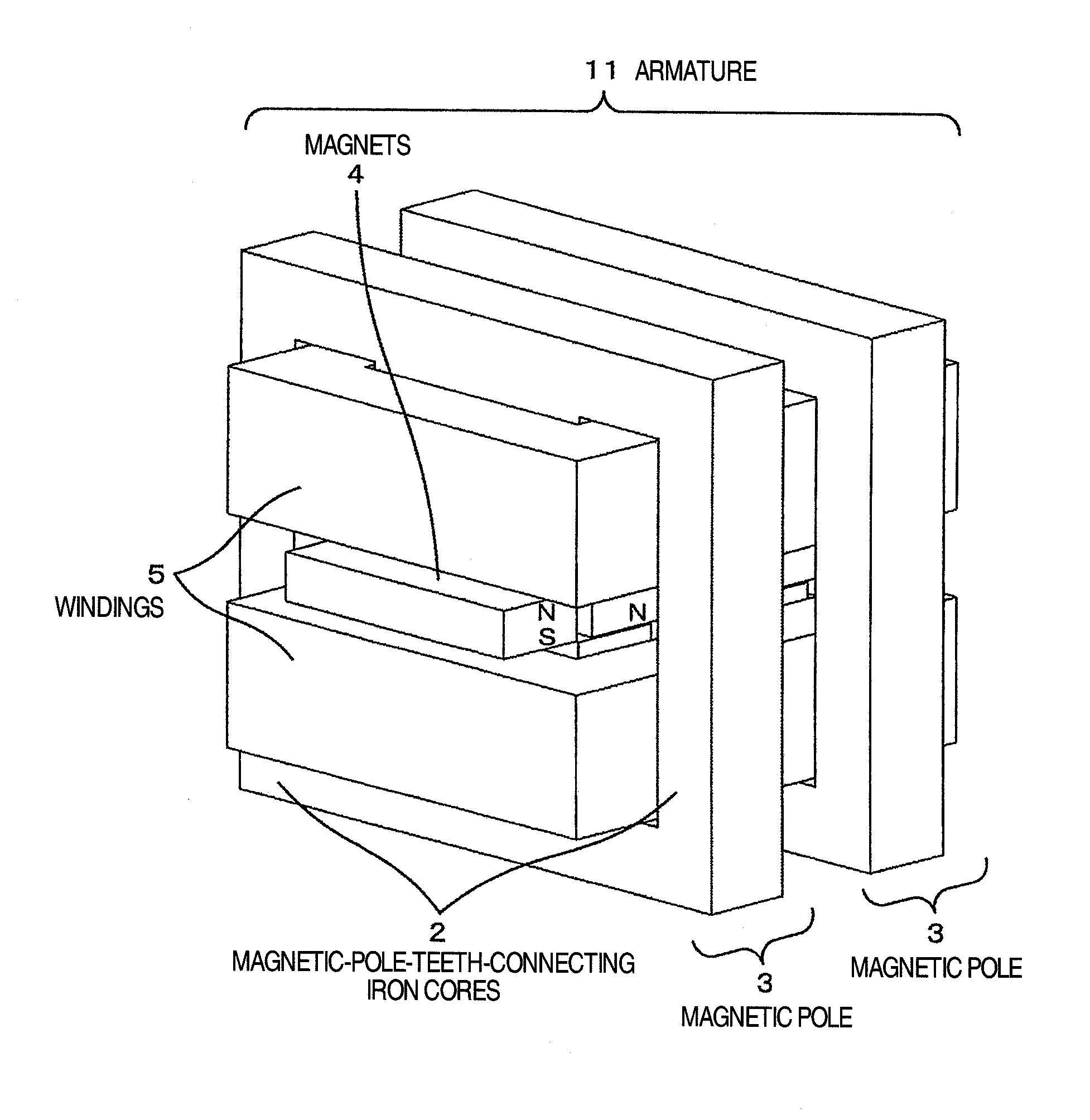
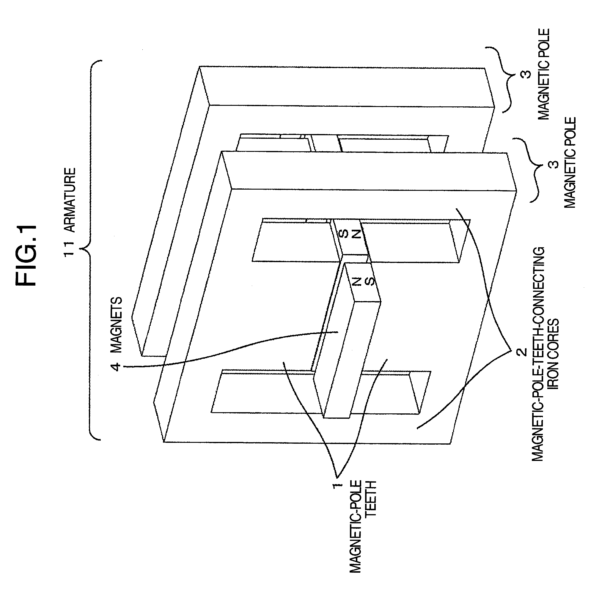
[0051]The description will be given below regarding an embodiment of the present invention. FIG. 1 illustrates the relationship between magnetic poles 3 and permanent magnets 4, both of which constitute an armature 11 of the linear motor according to the embodiment of the present invention. With respect to a magnet array where N poles and S poles of the magnets 4 are arranged in an alternate manner, magnetic-pole teeth 1 are set up over and under the magnets 4 in such a manner that the magnetic-pole teeth 1 sandwich-hold the magnets 4. A magnetic pole 3 is constituted with the upper-side and lower-side magnetic-pole teeth 1 and an iron core 2 for connecting these magnetic-pole teeth 1 to each other. Although, in FIG. 1, a case of the two units of magnetic poles 3 is illustrated, the number of the magnetic poles 3 is not limited thereto.

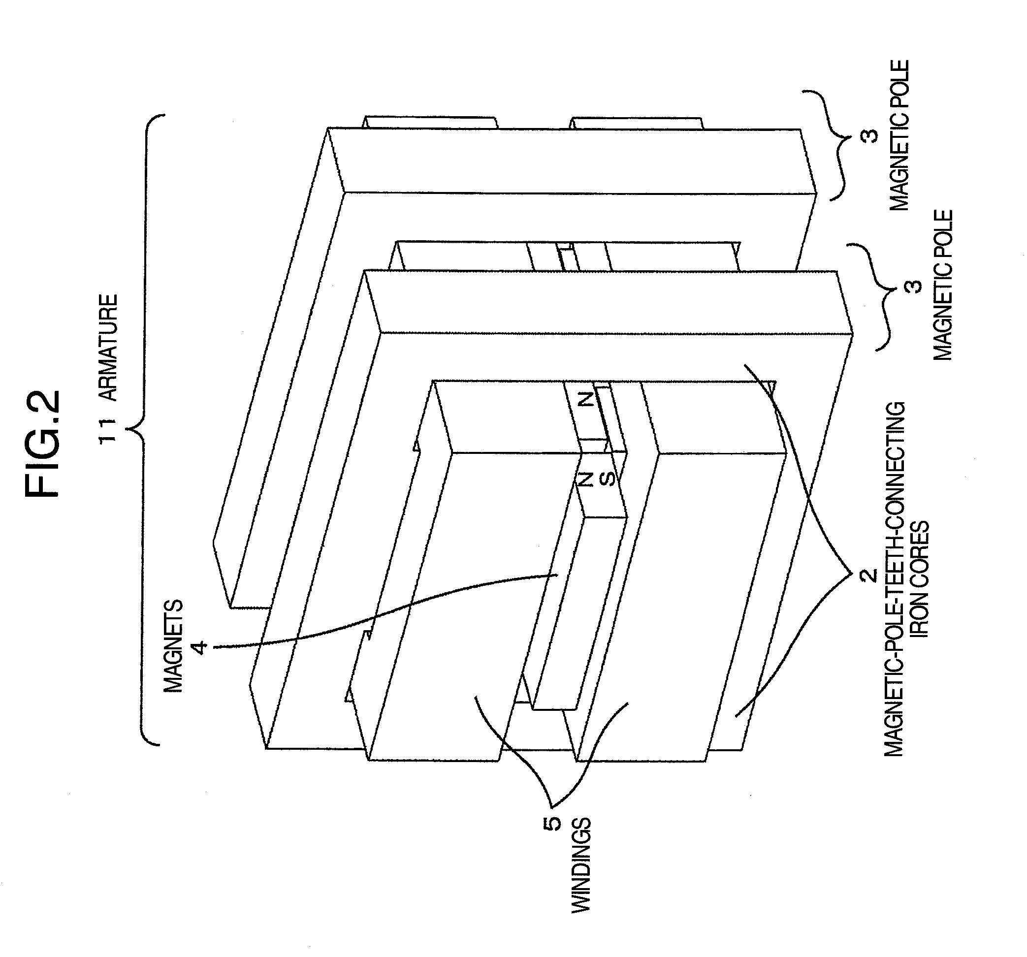
[0052]FIG. 2 is a diagram for illustrating the detailed configuration of the armature 11. Namely, windings 5 are further included, and are combined w...

2nd embodiment

[0059]FIG. 7 illustrates a second embodiment of the linear motor of the present invention. In FIG. 1, the case of the armature 11 including the two units of magnetic poles 3 has been illustrated. Also, the single magnetic pole 3 is constituted with the magnetic-pole teeth 1 and the iron core 2 for connecting these magnetic-pole teeth 1 to each other. In FIG. 7, however, a case of the armature 11 including the four units of magnetic poles 3 is illustrated. Each of the magnetic poles 3 is configured by multilayering a plurality of thin plate-like magnetic poles. Also, the magnets 4, which are fixed onto a magnet case 6, are arranged in the Z direction such that their N poles and S poles appear in an alternate manner. Flowing an electric current along the windings 5 in this state causes a force to be exerted onto the magnets 4, thereby giving rise to the generation of a Z-direction-oriented thrust. This Z-direction-oriented thrust makes it possible to displace the displacer which inclu...

3rd embodiment

[0061]FIG. 10 illustrates a third embodiment of the linear motor of the present invention. FIG. 10 illustrates the case where the four units of magnetic poles 3 illustrated in FIG. 1 are deployed. Here, the configuration components in the armature are deployed as follows: Namely, with reference to the pitch P between the magnets 4 (i.e., magnet pitch P), the pitch T between the magnetic poles 3 (i.e., magnetic-pole pitch T) is made equal to 2nP (n=1, 2, 3, . . . , i.e., arbitrary integer). In FIG. 10, n=1 is set. When the magnetic poles 3 are deployed on each 2nP basis, the thrust becomes equal to its maximum value. Consideration, however, is given to the case where the magnetic-pole positions are shifted in order to reduce the pulsation of the thrust or the like. In this case, in order to implement the reduction effect on the pulsation component of the thrust corresponding to a lowering in the thrust, it is the most advisable to set the adjustment width d of the magnetic poles 3 in...


PUM


Abstract

A linear motor including magnetic-pole teeth which pinch and hold permanent magnets deployed in a displacer, a plurality of iron cores used for continuously connecting the magnetic-pole teeth, windings wound around the plurality of iron cores in batch, and the displacer in which positive and negative magnetic poles of the permanent magnets are arranged alternately. A plurality of magnetic poles including the magnetic-pole teeth and the iron cores are deployed along a longitudinal direction of the displacer. The windings which are common to the plurality of magnetic poles are deployed on the iron cores. The leakage magnetic flux between the adjacent magnetic poles is reduced by making polarities of the plurality of deployed magnetic poles one and the same polarity.

Description

BACKGROUND OF THE INVENTION[0001]The present invention relates to a linear motor for generating a thrust.[0002]A linear motor which is equipped with the conventional thrust-generating mechanism has such a profile as being obtained by cutting and opening a rotating motor. Moreover, a large magnetically-attractive force is exerted between its displacer, which is constituted with an array of permanent magnets, and its armature. In JP-A-2001-028875, there is disclosed a linear motor where, in order to cancel out the magnetically-attractive force, magnetic poles having a first polarity and a second polarity are deployed in an alternate manner. In the conventional technology, as illustrated in FIG. 4 of JP-A-2001-028875, adjacent magnetic poles of the magnetic poles arranged in a travelling direction of the displacer have mutually different polarities.SUMMARY OF THE INVENTION[0003]In the conventional technology, adjacent magnetic-pole teeth of magnetic-pole teeth arranged in the travellin...

Claims


Application Information

Patent Timeline
Patent Type & Authority Applications(United States)
IPC IPC(8): H02K41/03
CPCH02K1/146H02K1/278H02K2213/03H02K41/031H02K16/00
Inventor AOYAMA, YASUAKI
Owner HITACHI LTD
Why Eureka
Try Eureka