

Halbach disc type magnetic coupling
A magnetic coupler and disc type technology, which is applied in the field of new disc magnetic couplers, can solve the problems of air transmission gap flux density, low utilization rate of permanent magnets, thick guide discs, and limited coupler applications, etc.
- Summary
- Abstract
- Description
- Claims
- Application Information
AI Technical Summary
Problems solved by technology
Method used
Image

Examples
Embodiment Construction
[0027] The specific implementation manners of the present invention are explained below in conjunction with the accompanying drawings.
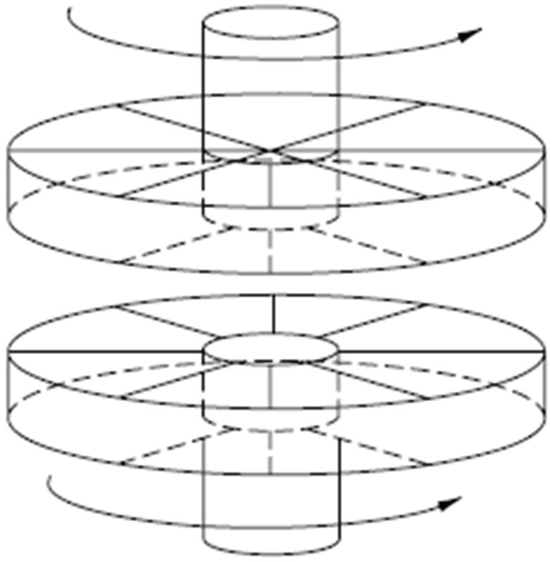
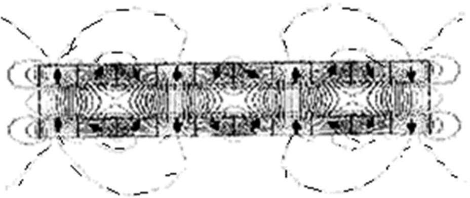
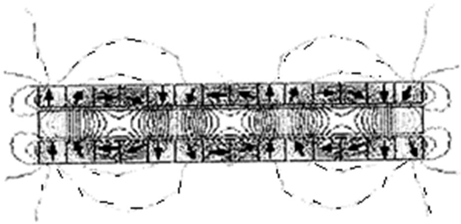
[0028] See attached Figure 5 , a Halbach disc magnetic coupling, comprising a driving disc 51 fixed by a driving shaft 53 and a driven disc 52 fixed by a load shaft 54, the driving disc 51 comprising a disc body (not labeled) and a Halbach column permanent magnet 512 The permanent magnets 512 of the Halbach row are arranged on the surface of the disc body facing the driven disk 52, the permanent magnets 512 of the Halbach row are evenly distributed around the driving shaft, and the magnetization direction of the permanent magnets 512 of the Halbach row is along the axial direction ( See Figure 7 ).
[0029] The Halbach disc coupler of the present invention includes a driving disc 51 , a driven disc 52 , a driving shaft 53 and a load shaft 54 . A Halbach column permanent magnet 512 is glued on the driving disk 51 and is connected with t...
PUM
 Abstract
Description
Claims
Application Information